It's been a while since joined , and thanks to the forum and
good material (D. Self's handbook), I've finally gotten this far.
There are good amps here, ..and great amps here. But none
as good as one you do yourself. (DIY "spirit")
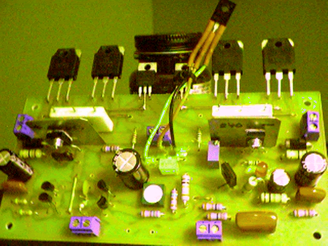
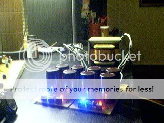
Well , here it is , not simulated, but a real working amp...
Another "blameless" design ,but with economical considerations.
(amp in picture below cost $21 US dollars)

I am continuing my work on the board layout in eagle 5 (source
of schematic) and would be very thankful if someone could
help me with some of the layout issues.
I have a full protection package in the design stage as well
as the layout for the PS completed.

Also ,comments or suggestions are always welcome.
OS
good material (D. Self's handbook), I've finally gotten this far.
There are good amps here, ..and great amps here. But none
as good as one you do yourself. (DIY "spirit")
Well , here it is , not simulated, but a real working amp...
An externally hosted image should be here but it was not working when we last tested it.
)An externally hosted image should be here but it was not working when we last tested it.
Another "blameless" design ,but with economical considerations.
(amp in picture below cost $21 US dollars)

I am continuing my work on the board layout in eagle 5 (source
of schematic) and would be very thankful if someone could
help me with some of the layout issues.
I have a full protection package in the design stage as well
as the layout for the PS completed.

Also ,comments or suggestions are always welcome.
OS
You need to simulate this
to be able to tell the specs 🙂 in a more impressive way 😀
I say you are a very quick learner, OS
And when being as interested and active as you are
you become good .. quickly.
Who knows where you will be in you designs in say 20 years.
Having the experience like Curl / Self / Pass.
If I may live as long to see .. I will know
Great job! Well done!
Thanks, lineup. I have done simple sims in spice but
dont know where to get models or how to import them
into spice for my devices.
I spent too much time with eagle and doing real world
sims with real parts.
I have scoped it ,(picoscope), it performs very good in
squarewave and sine tests.
>125w 8R0 (> 200w peaks with music content)
I was too impatient and after biasing hooked it right
to a speaker.(sounds great)
OS
yes, this is the hook, to get those models
most of the time I have to stick to 'similar' components
of course, I was ironic when say you have to sim 😉
we should not tease the man in brasil too much ...
And nothing beats real life test results ... or better Music with your own Amp 😎
... even dummy load test is questionable .. as this is not same loading as speakers
I got as far as simulating this with old 15003/4 devices
, but I use the new njw0302/0281's which are more
linear, lower Cob, (and cheap).This also helped me set
the currents of LTP and VAS.
I used picoscope to choose Cdom @68pf (best squarewave).
little ringing and NO oscillations. (don't like burning amps)
OS
, but I use the new njw0302/0281's which are more
linear, lower Cob, (and cheap).This also helped me set
the currents of LTP and VAS.
I used picoscope to choose Cdom @68pf (best squarewave).
little ringing and NO oscillations. (don't like burning amps)
OS
Yeah! Where is the improvrd mirror?😀
Good looking design, Cascoding the current source on the differential usually helps.
Regards,
Jam
Good looking design, Cascoding the current source on the differential usually helps.
Regards,
Jam
by jam - Yeah! Where is the improvrd mirror?
I didn't want to threadjack that from the CM thread.
What I'm going to do is incorporate the extra pads
in my final board layout to accept ALL the mods discussed in
the CM thread.🙂
As a "base" design it has a neutral quality and is very
sound (derated , failure anticipation).
Example :If the Vbias wiper fails - outputs go underbias,
baker clamps,OP section fails - only 100R resistors burn,etc.
But , here is the mod....
An externally hosted image should be here but it was not working when we last tested it.
by lineup - How much bias do you use for those .22 Ohm resistors
35ma per device (Xover "glitch" disappears at 20ma).
For that "eerie" (depth and decay) sound. 😀
OS
Frugalamp
ostripper
Are you able to post the LTP collector voltage readings, before and after the 3 transistor CM ? THis would give a very good idea of the differences between the 2 types, and the degree of balance achieved.
Regards
SandyK
ostripper
Are you able to post the LTP collector voltage readings, before and after the 3 transistor CM ? THis would give a very good idea of the differences between the 2 types, and the degree of balance achieved.
Regards
SandyK
Hi OS,
You're having fun now.
I like the choice for differential pair - I have a multitude of these salvaged from old Kenwoods myself.🙂
BD139 for the CCS on the input is different. Why is R8 1 watt?
I may sim this to see how it looks in virtual reality. 🙂
You're having fun now.
I like the choice for differential pair - I have a multitude of these salvaged from old Kenwoods myself.🙂
BD139 for the CCS on the input is different. Why is R8 1 watt?
I may sim this to see how it looks in virtual reality. 🙂
Ostripper
Where in TN are you located (if you don't mind saying)? If you are near Nashville I would be interested in helping with board layout or simulation. I also have a great wealth of parts you might find useful. I am not selling parts, I just like to meet and help out DIY people.
Steve Dunlap
Where in TN are you located (if you don't mind saying)? If you are near Nashville I would be interested in helping with board layout or simulation. I also have a great wealth of parts you might find useful. I am not selling parts, I just like to meet and help out DIY people.
Steve Dunlap
MJL21193 said:
I may sim this to see how it looks in virtual reality. 🙂
Looks pretty good! Seems to run fairly stable, though this looks like it could be improved by getting rid of R9 and C3 (what is this RC for?).
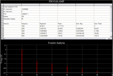
Here a 1k THD, if you're into that sort of thing🙂
Attachments
I've done similar things myself and they work well 🙂
I'd stick with the regular current mirror in the LTP. Also the current sink for the LTP doesn't need to be a BD139, you can use a BC546 just fine.
It is worth using the Self emitter follower VAS for the cost of an extra transistor.
58V is a bit high for just two pairs of outputs. Reduce it to 48V or add another pair.
jaycee said:
I'd stick with the regular current mirror in the LTP.
The simulated difference between the regular Widlar and the three T version (Glen's suggestion) show a THD increase from .085% to .086%. Otherwise identical, so I can't see how this would sound much different.
A worthwhile improvement would be to EF the VAS as jaycee says and swap that MJE350 for something better. The 2SA1381 that I'm using shows distortion dropping to .009% when used in your design. It's readily available and cheap.
MJL21193 said:
The simulated difference between the regular Widlar and the three T version (Glen's suggestion) show a THD increase from .085% to .086%. Otherwise identical, so I can't see how this would sound much different
I offered the 3-T current mirror as an alternative to that diode thing in another thread and further on made clear my opinion on the general worth of implementing it.
Also, you can't take that single pair of sim THD figures to mean too much (resolution too low to show the real [next to nada]effect of the improved mirror).
Cheers,
Glen
MJL21193 said:Looks pretty good! Seems to run fairly stable, though this looks like it could be improved
by getting rid of R9 and C3 (what is this RC for?).
It is a filter link that I think has to do with adjusting phase shift.
Not that I know exactly.
We can see this filter sometimes in Very Serious Hi-fi amplifiers!
😉
Frugalamp
jaycee and mjl21193
It's more about equalising the currents more closely in both halves of the LTP. Ostripper has already confirmed audible benefits by doing so.
See the "Current Mirror Discussion" thread.
It should also be noted that Glen has consistently posted negative posts about this area of investigation in the CM thread.
I believe that Ostripper should be permitted to continue this thread, and post his own conclusions without negativity from the more highly technically qualified members,before they find fault with his methodology.
SandyK
G.Kleinschmidt said:
I offered the...
Now, don't get your panties in a bunch Rachel. 🙂
I know your opinion, I'm just trying to do a little myth-busting. My point: how can it sound better?
The increase in distortion was not a slight on my part (it's only a difference of .001%). I'm sure it could probably be implemented to lower THD.
Re: Frugalamp
Just for fun, I'll note that the current mirror currently celebrated as the most sonically satisfying by more than one member is the 3-T version suggested by yours truly.
Bye bye,
Glen
sandyK said:See the "Current Mirror Discussion" thread.
It should also be noted that Glen has consistently posted negative posts about this area of investigation in the CM thread.
Just for fun, I'll note that the current mirror currently celebrated as the most sonically satisfying by more than one member is the 3-T version suggested by yours truly.
Bye bye,
Glen
- Status
- Not open for further replies.
- Home
- Amplifiers
- Solid State
- The Frugalamp by OS
