Frugalamp
ostripper
Something doesn't sound quite right about your input from the soundcard.
As an example, the new Silicon Chip ULD2, uses +-55V rails, has a gain of 24.5, and an input sensitivity of 1.26V for
125W into 8 ohms. Perhaps someone more familiar with PC audio would care to chip in ? You could of course, also try 39K instead of 33K, and see if that helps a bit.
SandyK
By mjl - If you don't like an EF on the VAS, changing the VAS to the 2SA1381 (as jaycee suggests, and me previously) will make a large improvement. This is worth doing.
On the subject the VAS , your 2sa1381/2sc1503 looks like it
is faster, same package,lower Cob, but only 100ma Ic.
that is why it modeled better with this amp.
The mje350 is a bigger, older, slower device having an Ic of
500ma. thats why I wondered when you mentioned mine
maybe getting hot at 14mA..
 Actually it runs just warm
(35C) firmly in class A (even with those little 1" aluminum sqaures).
Even your 1381 should not "sweat" 14 mA, well within SOA.
BTW I might be able to steal some 1381's out of all the CRT's
laying around (they are RGB amps , common)
OS
Something doesn't sound quite right about your input from the soundcard.
I'm kind of sure it's the sound card , its an old recycled PCI 128
(circa 1999). I gave my good ones.. audigy/SB live to the kids
for gaming.
I'll swap to make sure.
So you know , I'm totally PC based no DVD, CD, all FLAC,MP3,
divX for movies, can play the same songs (40K on network) on
all the DIY amps
simultaniously ,I do it for a living...
The old junk soundcard I'm using uses a 4.7uf 16NP
cap right at its outputs, new ones are direct low noise op-amp
based.
You might well find some suitable VAS devices in old CRT's, although where such devices would've been used, you now typically find an IC such as an LM23xx or LM24xx.
14mA through the VAS sounds like a lot to me, typically I would go for 7-8mA.
I keep looking at different techniques and never get to finally making something! I've looked at a number of input stages (my current favorite being the CFP input stage eg Cyrus One), single ended vs differential VAS, and EFII vs Triple Darlington output stages.
I should just stop fiddling and start making 🙂
ostripper, i'd be shocked if your card can't do at least 1V RMS. If sound quality is what you want though, forget Creative's junk. M-Audio Audiophile 2496 is pretty good, if you can get one.
I keep looking at different techniques and never get to finally making something! I've looked at a number of input stages (my current favorite being the CFP input stage eg Cyrus One), single ended vs differential VAS, and EFII vs Triple Darlington output stages.
Well this is the thread you get to see it done, frugal II is in the
works.. Differential VAS w/ CM too ..lots of balance.
Frugal I is a success , idiotproof and good sounding. A good
stepping stone. Might also go CFP with FA II(physically makes
biasing easy).
Don' t feel bad , I looked at many techniques (quasi, etc)
before I chose one. Like the Quasi ,this one works. I even
hooked 2 pairs of speakers to those little NJW OP'S ,
cranked it all day, It got hot but didn't blow.
Round up all your local E-garbage... Old receivers(trafo's),
P4 PC's (heatsinks) a chunk of FR-4 and 70$ parts.. all set.
BTW , how 'd you know, I'm getting one for XMAS (M-audio
5.1 w/envy24 chipset, same as audiophile 24 but cheaper)
OS
Yep, your design is actually remarkably similar to some things i SPICEd a while ago.
The M-AUDIO cards are good cards as theyre designed for pro musician use. Creative are designed for gamers, and the rest are usually for people who are happy if their PC makes a noise.
The ULTIMATE answer of course, is an external DAC, but lets not go there 😉
I already recycle loads of stuff. It drives my girlfriend mad 🙂 Right now i've got an old Teac amplifier which has provided me with some nice heatsinks and some good parts. I've got a 2x35V 500VA toroid, some 15,000uF 80V capacitors, got some pcb etc... really i just need to DO it 🙂
I already recycle loads of stuff. It drives my girlfriend mad Right now i've got an old Teac amplifier which has provided me with some nice heatsinks and some good parts. I've got a 2x35V 500VA toroid, some 15,000uF 80V capacitors, got some pcb etc... really I just need to DO it
you could build either of these , I first fired them up on a lower voltage 40-0-40VDC, they worked great..
Heres the latest greatest, it sims better than FA 1...
An externally hosted image should be here but it was not working when we last tested it.
I will make board tomorrow,
We will have balance....
OS
lineup said:One thing you can try later, if you wish,
is to add input bias current with compensation feature.
--------
And here is my old topic with schematics how we arrange a nice
input bias current cancelling:
Amplifiers >Solid State >Offset Correction using Bias Compensation
http://www.diyaudio.com/forums/showthread.php?threadid=71055
ostripper said:I see the advantages to this,active DC biasing instead of
passive. My only issue with this is:
What happens if it fails, DC ..bang,added trannies (but they are
frugal - $.04)
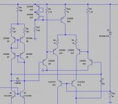
ostripper said:Heres the latest greatest, it sims better than FA 1...
http://i302.photobucket.com/albums/nn112/ostripper/frugal/frugalamp2.jpg
I will make board tomorrow,
That bias, as I said, try it later. I had no thought you should complicate this frugal amp. But maybe for some later project.
What happens if it fails? .... Not a good question 😀
Because no greater chance this addon bias will fail, than anything else in your amplifier may fail.
I prefer this adjustable offset without feedback, than having some offset SERVO Op-amp feedback loop, that may fail 😀 😀
What are the final changes you have done to your latest version?
In the VAS mirror you use 1N4004 rectifier diode.
Those are for rectifier bridge and power supply.
For audio signal, we use signal diodes 1N4148 (1N4448 for higher current).
They cost nothing 😀
Those are for rectifier bridge and power supply.
For audio signal, we use signal diodes 1N4148 (1N4448 for higher current).
They cost nothing 😀
Frugalamp
lineup
It's not feasible at these much higher rail voltages, but some years ago, with a phono preamp using an SSM2220 LTP,
and +-15V rails , I achieved a very good null of the offset, simply by connecting a 20M 1% resistor between collector and base of the input device. The directly coupled MM cartridge then had virtually no DC through it.
SandyK
ostripper said:
you could build either of these , I first fired them up on a lower voltage 40-0-40VDC, they worked great..
Heres the latest greatest, it sims better than FA 1...
OS
A few immediately obvious errors (as is is it won't work, so don't trust the sim too much).
There will not be enough voltage drop developed by the LTP current mirror to forward bias both series Vbe junction of the EF buffered VAS. Also, tail resistors are generally not bypassed.
Attached below is screen shot of a design of mine with a similar VAS. The LTP current in this case is 10mA. To get the required voltage headroom R5 is inserted. With this kind of arrangement the AC signals at each side of the LTP current mirror are not balanced. This is why I used a current source for the differential VAS tail; to avoid common mode distortion.
Clamp diode D1 is also necessary to limit the differential input voltage applied to the VAS when the amplifier is clipping.
This VAS arrangement requires a separate (higher voltage) supply rail from the output stage also.
I found that this arrangement (despite the odd look) works well with very low distortion. Have fun

Cheers,
Glen
Attachments
Just an observation, but the voltage gain of the inverting side of the input pair is very low compared with the non-inverting side. because the dynamic impedance of the current mirror input is low, compared to the output impedance.
It will work, but you aren't really driving the VAS with equal / balanced signals.
It will work, but you aren't really driving the VAS with equal / balanced signals.
To address both problems , why not drop the CM altogether
replace with 2K2 resistors. (get my parts count down too).
(Q3 and Q4) VAS idea was ported from old HH scott amp
running at + - 90 V.
I guess I'll have to really build it...
OS
replace with 2K2 resistors. (get my parts count down too).
(Q3 and Q4) VAS idea was ported from old HH scott amp
running at + - 90 V.
I guess I'll have to really build it...
OS
replacing the input current mirror with resistors is the usual solution, it also makes calculating the bias voltage for the VAS much easier.
🙂
🙂
Agree strongly, usual solution is to delete the CM, replace with resistors. Works very well providing stage current is well controlled and LTP base bias is equal both sides with good beta and impedance matching.
However, this will alter OLG of the LTP, in turn changing compensation by reducing fb factor. You will need to reduce the lag compensation to accommodate this change.
Congratulations, OS, this is looking good....
Hugh
However, this will alter OLG of the LTP, in turn changing compensation by reducing fb factor. You will need to reduce the lag compensation to accommodate this change.
Congratulations, OS, this is looking good....
Hugh
Yes, you could, and if you do, you have replicated the Hitachi Application Note from 1972 which was developed for their new mosfets, and which is used in many Class AB Pro-audio amps because it is rugged, dependable, and inexpensive!
Nothing is new under the sun......
Hugh
Nothing is new under the sun......
Hugh
By AKSA - You will need to reduce the lag compensation to accommodate this change.
Explain further...
BTW, FA1 is sounding wonderful (w/diode CM)
OS
Lag compensation is a means used to pull back OLG by the pole frequency to avoid instability. Typically it's a cap between collector and base of the VAS device(s).
In your circuit you have used 47pF on one side only. If you dispense with the CM on the LTP, you will reduce OLG, and somewhat relax the compensation. I would be thinking about making it symmetrical, that is a cap on active AND drone side.
Try for equal values at first, then do some simming for lower values on the drone side.
Further, you should consider around 47nF instead of 470pF for C14 on the drone side....
Hugh
ostripper said:
On the subject the VAS , your 2sa1381/2sc1503 looks like it
is faster, same package,lower Cob, but only 100ma Ic.
that is why it modeled better with this amp.
The mje350 is a bigger, older, slower device having an Ic of
500ma. thats why I wondered when you mentioned mine
maybe getting hot at 14mA..
(35C) firmly in class A (even with those little 1" aluminum sqaures).
Even your 1381 should not "sweat" 14 mA, well within SOA.
BTW I might be able to steal some 1381's out of all the CRT's
laying around (they are RGB amps , common)
OS
The VAS doesn't leave class A, as it doesn't switch off. Finding the current that it works most efficiently at is the key. You will cut distortion by a good margin by lowering that 14mA to ~8mA.
That 35*C is at idle? Mine, running at ~8mA gets much hotter than that during normal operation and that's with a small heatsink.
Moving on to a new design already? There are still places you can go with the "old" design to improve it. Working up an even more complicated scheme just increases the magnitude of other problems (stability, distortion) to essentially do the exact same job as a optimized , less complex design.
- Status
- Not open for further replies.
- Home
- Amplifiers
- Solid State
- The Frugalamp by OS