ostripper said:Share ..man , Share. I have both running simutaniously..
Here's what I did:
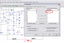
Add a AC signal voltage to the feedback loop (the red arrow in pic), right click this and st AC Analysis Magnitude to .5V, phase 0.
Ground the input.
Open the AC analysis sim and form the expression like I have in the pic (click "add expression" to do this), but using the nets in your schematic. Run it.
Attachments
Hmm, I may not have been as far off as I thought. I've been testing full power THD and mistaking the high readings as a simulator problem. I've now found that this is almost never done!
I'll have to get my hands on Multisim and have a good play.
ostripper and MJL21193, you two are seriously spoiling me for choice of designs here 😀
I'll have to get my hands on Multisim and have a good play.
ostripper and MJL21193, you two are seriously spoiling me for choice of designs here 😀
Jaycee..I'll have to get my hands on Multisim and have a good play..
Click that magic button at the bottom of my post...😀
ahh, I see that where that is in MS, I wonder if you could
create 2 custom nodes .. like a/b or x/y..
by JC - Hmm, I may not have been as far off as I thought. I've been testing full power THD and mistaking the high readings as a simulator problem. I've now found that this is almost never done!
Use andy's sine gen. (post 466) you will find the LT "fix"
look at my low and high power test after..😎
OS
MJL21193 said:I went back through this thread to where Andy first demonstrated the method to you. I have LT4 on this computer (never used) and i looked through the tutorial. Took a while to figure out how to do the same in MS, but I got there.
Just another weapon in my arsenal. 🙂
Hi John,
Just a minor nitpick. It looks like you are plotting -AB rather than AB. When the amp simulation is correctly configured for negative feedback and it shows the amp as working, the phase of the loop gain AB should be 0 deg at very low frequencies. Then as frequency increases, it should become negative, eventually hovering at -90 deg over a broad frequency band, then finally falling more negative than that in the MHz region. So you need to put a minus sign in your loop gain computation. Not a big deal at all, but just keeps things consistent with what OS is doing.
Yes, it looks like he should put a (-) before his "net2"..
I just did it and produced a exact copy of my lt one.
OS
I just did it and produced a exact copy of my lt one.
OS
andy_c said:
It looks like you are plotting -AB rather than AB.
Thanks again Andy,
I have it straightened out now. I didn't even notice the phase was reversed 😱
Better?

MJL21193 said:Thanks again Andy,
I have it straightened out now. I didn't even notice the phase was reversed 😱
Better?
Looks really good. I would not try to lead compensate this bad boy, as the magnitude looks picture perfect. Lead comp would flatten out the high-frequency loop gain and likely degrade the stability.
Now that you guys are no longer using LTspice, I think I will go back to my own project, which is being neglected at the moment 🙂.
ostripper said:Multisim 8 does not have "add expression" in the ac analysis
GUI like your version does...
Look up "Circuit Design Suite" on your favorite search sites 🙂. That's the latest and greatest name.
jaycee said:I still get the "noise" with BD139/140, but I don't get the nasty, spiky behaviour. However, the KSA1381/KSC3503 models have worked in the past. Likewise, thsi is the first time I've seen the "noise". Something's definitely changed in LTSpiceIV to cause this
Maybe too little too late, but try edit model and delete (or comment) QCO=0.05 and RCO=50.1187. For me that helps much (in LTSpice). More details here: http://www.diyaudio.com/forums/showthread.php?postid=1686931#post1686931
andy_c said:
Looks really good. I would not try to lead compensate this bad boy, as the magnitude looks picture perfect. Lead comp would flatten out the high-frequency loop gain and likely degrade the stability.
I think I will go back to my own project, which is being neglected at the moment 🙂.
Thanks Andy,
Very good performance in real life too - very stable.
Don't go too far, we will funk up somewhere else and the same advice and fixes apply to both.
🙂
By andy - Now that you guys are no longer using LTspice
I will still use it. LT is like win XP, as multisim is like Veeeesta
(win Vista) LT's FFT has more resolution... but multisim has
more toys.
OS
ostripper said:
LT's FFT has more resolution...
That's only the way it appears, as MS just shows the magnitude of the harmonics and not the hash between. I believe it is every bit as accurate and resolved as LT's.
With that said, I don't think you can put too much faith in this. The overall THD yes, but the distribution of harmonics should be used as a rough guide only and not gospel.
I changed FA3 (again,updated every instance of it)..
Went back to the good old "blameless", tacked on some
cascodes and widlars and finally have a amp that
will take any model.. ksa1381,mje350,BD-XX, or even the
new one, KSA1221(what a squirrely device)...

With 4 different devices it clips the same (symmetrically and
without sticking/saturation)
has the same UGP, and almost non-existant H2/3/5 (sub .001%)
To be sure I did this one on both LT4 and NI circuit design suite
10 (ahem)..
Sometimes simple IS better..
OS
Went back to the good old "blameless", tacked on some
cascodes and widlars and finally have a amp that
will take any model.. ksa1381,mje350,BD-XX, or even the
new one, KSA1221(what a squirrely device)...
With 4 different devices it clips the same (symmetrically and
without sticking/saturation)
has the same UGP, and almost non-existant H2/3/5 (sub .001%)
To be sure I did this one on both LT4 and NI circuit design suite
10 (ahem)..
Sometimes simple IS better..
OS
Hi OS,
A couple of things...
C6 and C9 should not be in parallel with R2 and R6. They will actually degrade PSRR in the positions shown.
Q3 has very low dissipation, so it can be a TO-92 device.
A couple of things...
C6 and C9 should not be in parallel with R2 and R6. They will actually degrade PSRR in the positions shown.
Q3 has very low dissipation, so it can be a TO-92 device.
andy_c said:C6 and C9 should not be in parallel with R2 and R6.
Was going to post about C6, C9.
But I need not. Already done 😉
Was the only issue I could see, from a quick look
Regards, Lineup
By andy -C6 and C9 should not be in parallel with R2 and R6
What would be a better way to decouple the bias chain..
(D1,4,6,3..)??
Would it be better to let the whole thing "float". No ground reference??
Q3 has very low dissipation, so it can be a TO-92 device.
I want the ksa for its superior Hfe and Cob, not it's dissipation.
thanks.. (no EF needed)
OS
Split up R2 into 2 x 4k7. (or 2 x 5k6 for ~5 mA into diodes)
Put the C6 cap from between the two 4k7 to V+ supply.
(4k7//4k7) x 22uF, will give a lowpass RC filter at about 3 Hz
And of course do same thing for R6, C9 on the negative side.
Put the C6 cap from between the two 4k7 to V+ supply.
(4k7//4k7) x 22uF, will give a lowpass RC filter at about 3 Hz
And of course do same thing for R6, C9 on the negative side.
Ahh, do the "self thing ".. R-C-R😎(4k7//4k7) x 22uF, will give a lowpass RC filter at about 3 Hz
OS
- Status
- Not open for further replies.
- Home
- Amplifiers
- Solid State
- The Frugalamp by OS