I took a video that shows the cold power up behavior of my right channel F6 Diamond board. The two small meters are across the source resistors (left is 0R56 and right is 0R47)the larger Fluke is monitoring DC offset.
Input is shorted and chassis lid is installed just after power up (no rear panel). Regulated +/-28VDC rails and 1.7A bias current.
Well, this didn’t work. Video is 1min long and too large to send.
Input is shorted and chassis lid is installed just after power up (no rear panel). Regulated +/-28VDC rails and 1.7A bias current.
Well, this didn’t work. Video is 1min long and too large to send.
That would have been too much effort right before snoozing time, G. 😴
I’ve been playing around with transformers and a variac to dial in the rail voltage. The regulated psu needs about 1.5V max dropout to stay in regulation under all conditions throughout the yearly ups and downs of the power grid. The F6 Diamond is running at 1.75A bias current, any more than 1.5V drop and the regulator heatsinks get a bit too hot for my comfort zone.
For this scenario and 120V mains (measured), I need a transformer to deliver 25Vac under load at the psu input (Synchronous rectification used here).
The Antek AS-3224 delivers that perfectly when loaded with F6D board.
25Vac
31.45V at the first cap
30V output after adjusting regulator
At this voltage and current the source resistors are hot!
R1 and R1* are acceptable but, R2 is very hot running at 80°C+
@TungstenAudio, would a pair of 0R22 resistors in series work or use a quad of 0R47 wired in parallel/series be better since the outcome would still be 0R47?
Good to hear that report Vunce, I would say the last option you propose will be best as that would as you say still give you 0R47 - 4 off 3 watt resistors will bring the dissipation in each resistor down by 75%. Two 0R22 in series will give 0R44 - which might upset the bias somewhat.
Good to hear your progress, I wonder if TA has seen his R2 get that hot?
Good to hear your progress, I wonder if TA has seen his R2 get that hot?
So, with 1.75Adc bias you should be seeing something like 822.5mV across R2 being 0R47 - this gives a dissipation in R2 of 1.44 watts at that bias level - the data sheet for the resistor you have used should have a graph of temp vs watts to show a surface temp.
TA's pic shows Panasonic ERG 3 watt for R2. Your pic looks the same. The Panasonic data sheet lines up with the temp you show for that power dissipation.
The ERG's are rated up to 200 deg C surface temp on the graph - very toasty!!
TA's pic shows Panasonic ERG 3 watt for R2. Your pic looks the same. The Panasonic data sheet lines up with the temp you show for that power dissipation.
The ERG's are rated up to 200 deg C surface temp on the graph - very toasty!!
Last edited:

Yes, the 3W source resistors get warm. If you wanted to use a pair of 0.22 Ohm in series, that would work. I have also used Bourns 15W thick film resistors in a previous build, with their own heatsinks.
105 W per channel is what I am seeing as well. My chassis is not quite 4U high, but it is 400mm deep. I have augmented the sinks with aluminum L brackets. When running with 1.8A bias the sinks get plenty warm, but not too to hold.
105 W per channel is what I am seeing as well. My chassis is not quite 4U high, but it is 400mm deep. I have augmented the sinks with aluminum L brackets. When running with 1.8A bias the sinks get plenty warm, but not too to hold.

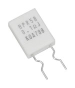
Guys, how about using 5 watt current sense resistors?
IIRC the KOA BPR series has a wide range of values, e.g. 0.22R, 0.33R, 0.47R, 0.56R that can be used.
IIRC the KOA BPR series has a wide range of values, e.g. 0.22R, 0.33R, 0.47R, 0.56R that can be used.
Attachments
Last edited:
This!The ERG's are rated up to 200 deg C surface temp on the graph - very toasty!!
Vunce, remember you are the one and only FEARLESS AMP BUILDER!
😈💪
P = I^2R = 1.75^2*0.47 = 1.44 watts as Gary stated.
That being said, I am using 5W resistors in my build ;-)
Best,
Anand.
Good call Zman, I would have used the KOA 5watters, but only had 0R1, 0R22 and 0R68 in the bins. Time to Add 0R47’s to my Mouser cart, they will be swapped in before the F6D leaves the bench 😉.
My chassis is handling the dissipation duties well, right in line with your observations TA. Actually, when I put the lid on last night the heatsink dropped 1-2°C, the thick front panel is helping out now.
My chassis is handling the dissipation duties well, right in line with your observations TA. Actually, when I put the lid on last night the heatsink dropped 1-2°C, the thick front panel is helping out now.
You also have these to pick from - I would choose the last one as they are non inductive.
https://au.mouser.com/ProductDetail/KOA-Speer/MOSX5CR47J?qs=PHXRRA1URyAQVJE5OFpRNg==
https://au.mouser.com/ProductDetail/Vishay-Draloric/PAC500004707FAC000?qs=IamZOtRiI5toDHiFBx0YSQ==
https://au.mouser.com/ProductDetail/Vishay-Draloric/AC05000004707JAC00?qs=9EcTHFQkrt89eb2J9Rg7Vw==
https://au.mouser.com/ProductDetail/KOA-Speer/MOSX5CR47J?qs=PHXRRA1URyAQVJE5OFpRNg==
https://au.mouser.com/ProductDetail/Vishay-Draloric/PAC500004707FAC000?qs=IamZOtRiI5toDHiFBx0YSQ==
https://au.mouser.com/ProductDetail/Vishay-Draloric/AC05000004707JAC00?qs=9EcTHFQkrt89eb2J9Rg7Vw==
That AC05 part is not non-inductive. Only the ‘-NI’ parts are non-inductive. For 5 waters the part number would begin as ‘AC05-NI’ …
I have been usung the KOA/Speer MOSX resistors lately in place of the older Panasonics. They have a higher tempco, consistent with metal oxide.
The Vishay wirewound at 100 ppm / K are a great choice here. We actually want the small positive tempco to keep the amp stable as it heats up.
The small negative tempco of the last parts will have a small tendency to increase bias current as the amp heats up - not what we want here.
The Vishay wirewound at 100 ppm / K are a great choice here. We actually want the small positive tempco to keep the amp stable as it heats up.
The small negative tempco of the last parts will have a small tendency to increase bias current as the amp heats up - not what we want here.
You are correct Marcus - can't find the NI types though.
Anyone know what the transconductance of 2SK2013/2SJ313 is, is it a suitable substitute for IRFP240? I ask because I have a few matched pairs…
nope, no go
xconductance easy to find in datasheet
just ggl "2sk2013 pdf"
xconductance easy to find in datasheet
just ggl "2sk2013 pdf"
- Home
- Amplifiers
- Pass Labs
- The F6 Revisited