Some more update on the Beta testers.
Both of them made a test setup (not final heatsinks, power supplies, etc.) and both have their F5Pi with MFB working.
Both are using Toshiba devices, one of them supplied by us, the other has his own.
At least one of them was able to repeat our results, 400kHz bandwidth and no ringing with 100kHz square wave into 8R//100n.

We'll wait a bit more till the 2nd also achieves the same.
Then we'll post Gerber files for the frontend and the OPS.
Won't be long.
Patrick
Both of them made a test setup (not final heatsinks, power supplies, etc.) and both have their F5Pi with MFB working.
Both are using Toshiba devices, one of them supplied by us, the other has his own.
At least one of them was able to repeat our results, 400kHz bandwidth and no ringing with 100kHz square wave into 8R//100n.
We'll wait a bit more till the 2nd also achieves the same.
Then we'll post Gerber files for the frontend and the OPS.
Won't be long.
Patrick

We have also now tested the F5Pi_US.
The square wave test was perfect.
No ringing into 8R // 100n or Stereophile dummy load.

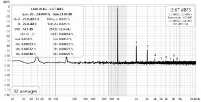
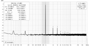
The distortion measurement was interesting.
In post #65, we showed the distortion spectrumm of the frontend on its own.
H2 was 0.014%, and H3 was 0,0053%.
But in the combination, H2 was reduced to 0.0046%, while H3 essentially the same at 0.0045%.
So some H2 cancellation is happening between frontend and OPS.
Maybe just the combination of this particular Q-set. Maybe not.
Sounds great also, I was told.
Patrick
The square wave test was perfect.
No ringing into 8R // 100n or Stereophile dummy load.
The distortion measurement was interesting.
In post #65, we showed the distortion spectrumm of the frontend on its own.
H2 was 0.014%, and H3 was 0,0053%.
But in the combination, H2 was reduced to 0.0046%, while H3 essentially the same at 0.0045%.
So some H2 cancellation is happening between frontend and OPS.
Maybe just the combination of this particular Q-set. Maybe not.
Sounds great also, I was told.
Patrick
Attachments
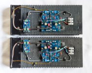
Some more pictures from Fran.
The F5Pi_US is almost complete, just pending the DC servo.
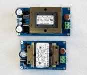
We also designed and tested new AUX PSU boards to use transformers available at Mouser.
And dual primary voltage for 115V and 230V.
Patrick
.
The F5Pi_US is almost complete, just pending the DC servo.
We also designed and tested new AUX PSU boards to use transformers available at Mouser.
And dual primary voltage for 115V and 230V.
Patrick
.
Attachments
Assuming negative feedback loop is closed in both cases, this is easily explained by the error signal Vi-β*Vo being amplified by the front-end stage which will contain the negative of the 2nd and other harmonics produced by the output state. Thus the front-end output can easily have significantly more distortion than the output stage. I can provide a full analysis if you are interested....
The distortion measurement was interesting.
In post #65, we showed the distortion spectrumm of the frontend on its own.
H2 was 0.014%, and H3 was 0,0053%.
But in the combination, H2 was reduced to 0.0046%, while H3 essentially the same at 0.0045%.
So some H2 cancellation is happening between frontend and OPS.
...
In order to really see the distortion level of the front-end you must open the feedback loop or wrap the loop around only the front-end.
So finally, after having the boards sent over to me, all the problems of the 2nd Beta Tester are sorted.
Fortunately not to do with the amp itself.
Shall give a detailed update tomorrow, followed by Gerber files.
Patrick
Fortunately not to do with the amp itself.
Shall give a detailed update tomorrow, followed by Gerber files.
Patrick
As promised a detailed update.
First technical :
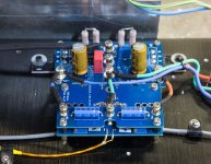
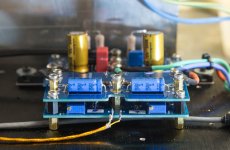
The two Beta testers have now fully functioning F5Pi amplifiers.
The first tester initially had some small ringing problems with square waves.
He took my advise to place the two PCBs close to each other, as I have shown in photos.
Added some 10,000µF caps close by, everything works as expected.
Sometimes you just need to take my word to read and follow instructions closely.
The second tester had a lot of stability problems with reactive load, not just ringing.
As we got nowhere doing remote debugging, the prototype was sent to me.
The problem was eventually traced down to a piece of thin coax cable he was using at the input.
Once that was removed, the amp behaves perfectly fine, at least with my signal generator and scope.
But I wanted to understand why this was the case.
So together with Fran, we did a LOT of experiments to figure out.
One can see that the ringing was not only at the output, but also at the input.
We tried soldering an extra resistor (from 500R to 10k) at the output pin, and the ringing was gone completely.
We then removed the original Ri1 and replace with 5.6k, and the ringing reappeared at the input.
Using a normal scope probe to the signal generator and amp input, and all is fine again.
What does that tell us ?
The ringing comes from the digital signal generator, probably cable reflections interacting with its output stage.
Frequency sweep of the amplifier all the way up to 3MHz shows smooth drop off at 400kHz with no humps.
Replace the digital signal generator with an analogue one, and 100kHz square wave was absolutely smooth.
I could have played safe by reducing closed loop bandwidth with 1nF feedback caps.
But I don't want to.
If all the above means nothing to you, my advice is "don't take this on".
You need to have quite some understanding and experience to sort out these issues, plus suitable equipment.
Relying on me or others to remote debug will NOT work.
You are much better off with projects from the DIY Store, like the F5m.
You will be looked after from head to toe over there.
So you have been warned.
Patrick
First technical :
The two Beta testers have now fully functioning F5Pi amplifiers.
The first tester initially had some small ringing problems with square waves.
He took my advise to place the two PCBs close to each other, as I have shown in photos.
Added some 10,000µF caps close by, everything works as expected.
Sometimes you just need to take my word to read and follow instructions closely.
The second tester had a lot of stability problems with reactive load, not just ringing.
As we got nowhere doing remote debugging, the prototype was sent to me.
The problem was eventually traced down to a piece of thin coax cable he was using at the input.
Once that was removed, the amp behaves perfectly fine, at least with my signal generator and scope.
But I wanted to understand why this was the case.
So together with Fran, we did a LOT of experiments to figure out.
One can see that the ringing was not only at the output, but also at the input.
We tried soldering an extra resistor (from 500R to 10k) at the output pin, and the ringing was gone completely.
We then removed the original Ri1 and replace with 5.6k, and the ringing reappeared at the input.
Using a normal scope probe to the signal generator and amp input, and all is fine again.
What does that tell us ?
The ringing comes from the digital signal generator, probably cable reflections interacting with its output stage.
Frequency sweep of the amplifier all the way up to 3MHz shows smooth drop off at 400kHz with no humps.
Replace the digital signal generator with an analogue one, and 100kHz square wave was absolutely smooth.
I could have played safe by reducing closed loop bandwidth with 1nF feedback caps.
But I don't want to.
If all the above means nothing to you, my advice is "don't take this on".
You need to have quite some understanding and experience to sort out these issues, plus suitable equipment.
Relying on me or others to remote debug will NOT work.
You are much better off with projects from the DIY Store, like the F5m.
You will be looked after from head to toe over there.
So you have been warned.
Patrick
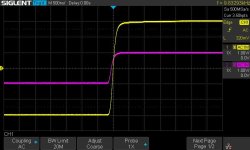
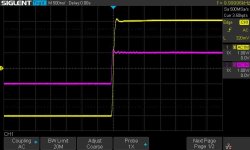
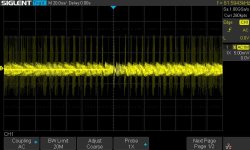
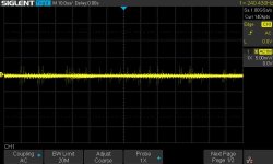
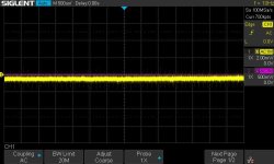
Here is what can be seen from Fran's Signal Generator.
First picture coax direct soldered, digital SG.
Second picture using Oscilloscope Probe.
Third picture Analogue SG.
Load in all cases 8R//100n.
Violet is input, yellow output.
Patrick
.
First picture coax direct soldered, digital SG.
Second picture using Oscilloscope Probe.
Third picture Analogue SG.
Load in all cases 8R//100n.
Violet is input, yellow output.
Patrick
.
Attachments

As both the F5 and the M2OPS are not my design, I shall publish the same Gerber files as the Beta testers.
These are simplified version of the one used in my prototype, which contains other options.
They have been used by the two Beta Testers and Fran.
There were no circuitry errors, just some labelling which are now revised.
But as always, you should not just solder blindly, but check PCB against schematics.
We shall only send off building instructions and bill of materials in paper form to avoid unauthorised copies.
So there will be a small charge for printing and postage from ireland, which will ensure they only get to serious builders.
(Many many thanks to Fran for taking care of all the donkey work nobody wants.)
This is meant for your own hobby use.
In case of any commercial exploitation, you are not violating my rights, but Nelson's, the originator of the circuits.
I am not posting the Gerber for the servo board just now.
My own test indicates that it is not necessary.
And you pay a distortion penalty with the servo, as Fran found out.
So you should only include DC servo if you have to (and then only in the Onsemi version).
Patrick
.
Attachments
We have now also completed all tests of the US version, as published earlier.
This uses 2N5457/5460 and FQP3N30/3P20 are the frontend.
Apart from somewhat higher distortion, this also has a slightly safer bandwidth at ~140kHz.
https://www.diyaudio.com/community/...tage-perfectly-integrated.406024/post-7573315
Still plenty for an integrated / power amplifier.
Both the JFET and MOSFET pairs are obsolete.
The JFETs, made by Central and not Onsemi, can still be ordered on request.
The MOSFETs are available at Rochester for moQ of ~500 pieces each.
We only have very few pairs of 2N5457/5460, and they are from central.
So we can only offer the Onsemi SMD version with adaptor PCBs instead, of which we have some 100 each from Mouser before they were obsolete.
Dissipation is no issue, as they will see < 40mW each, more like 20mW.
But with 100 pcs, matching yield is poor.
We only offer 10 sets of NP-NP match, and another 10 sets of NN-PP match.
We can also offer (Vgs and Yfs) matched quads of FQP30N30/30P20.
The N and P devices were from different distributors (i.e not all from Rochester), and we were lucky this time to have reasonable N-P yield.
If you purchase them both from Rochester, you might not have the same results.
We shall offer 20 sets of these as Q-set (a quad of JFETs and a quad of TO220 MOSFETs) in a later GB.
I think that will be more than enough for anyone seriously interested.
They will cost about half of what you need to pay for Toshiba JFETs and MOSFETs elsewhere.
You can get matched IRFP140/9140 from the DIY store for the output stage. Or as always, match your own.
Patrick
Both Beta tester have decided to set up their own amplifier configurations.
i.e. their own choices of power supply, volume control, etc.
That is of course what DIY is about, and absolutely fine with us.
While waiting for the Beta testers, a lot more work have been done in the background.
So we want to show us what is involved in our own solution.
Again many thanks to Fran for helping with the experimental work.
We mentioned in the article how we modified the Relaixed Passive from Jos van Eijndhoven :
http://www.vaneijndhoven.net/jos/relaixedpassive/index.html
So how did our solution compared with the original ?
Fran actually built a standard version of the Relaixed with SMPS.
The attenuator has a length of coax cable of about 100mm between PCB out and the scope probe.
And he is what he measured.
First picture is the baseline of the scope with probe shorted.
Second picture is the output of the Relaixed with input shorted. Only attenuator.
Third picture is the output of the Relaixed after it went into sleep mode.
Fourth picture is the output of the Relaixed in active mode, powered by linear regulated supply.
And finally, the last picture is the output of the F5Pi with the RCA input shorted.
The input noise is now amplified by 20x, in addition to the noise of the F5Pi itself.
Also note the different voltage scale in those pictures.
It is obvious that even in a relay operated attenuator, how the MCU and the relays are powered make huge differences.
Work is still ongoing to improve the capability of noise measurements, before more work can be done to see if noise can be improved even further.
Patrick
.
Attachments


How about Toshiba Q-Set ?
We can only offer a maximum of 20 sets of Toshiba devices, limited by our stock of 2SK2013/2SJ313 NNPP quads.
(We are just as happy if they are not taken up, since you get also get them elswhere.) 🙂
Each set consists of a quad of K170/J74, a quad of K2013/J313, and a quad of K3497/J618.
All curve tracer matched under temperature control at working conditions.
Note that K170/J74 & K3497/J618 are NOT true complementaries, so they are matched NNPP for Idss / Vgs.
And of course also Yfs matched between 2 Ns and 2 Ps.
These will have to wait till end of February, when all the backlog in the post in Hong Kong is cleared after Chinese New Year.
And PCB Set ?
Both Beta testers decided not to follow us for the rest.
So we shall only offer the complete solution on request (complete set of 22 PCBs as in our proto).
There has to be a minimum subscription of 10 sets before we shall make this avaiable.
You cannot imagine how much work it is to prepare all the documentations for public use.
So we shall only do this when there is sufficient interest.
Patrick
Sign me up!Each set consists of a quad of K170/J74, a quad of K2013/J313, and a quad of K3497/J618.
Regarding the PCB’s - all I require are F5p voltage gain stage and the M2OPS; either from you or I’ll just order through a fab since you have already kindly shared your gerbers on post #90.
Best,
Anand.
The development never stops. 🤓
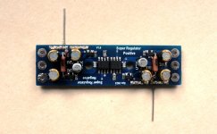
How much would the noise level of the amplifier reduce if we use a Didden Super Regulator for the frontend, maybe even the output stage ?
We made a stacker board which will convert our "standard" Cap Multiuplier board into a Super Reg.
Works on the bench. To be tested in the amplifier.
The pass device has to be either a Japanese power FET (with Vgs ~2.5V), or Sanken Darlingtons (hfe >> 1000 at 1A).
Patrick
.
Attachments
Hi all,
More subjective impressions from a recent session at a friends place. He has two different setups in two rooms - we listened in both to get an idea of how the F5Pi performed in each one.
In the first he has a pair of Spendor 9/1 (large 3 way top of the line speakers from the 90s), Musical Fidelity Nuvista M3, and then a variety of sources - Eversolo DMPA6 into Miro AD1862 dac, Garrard 301 with Cyrus phono stage etc. We focussed on the Eversolo/Miro DAC combo as it gave us the opportunity to throw lots of different tracks at it. The F5Pi excelled here - detail and soundstage really stand out here. The Nuvista is no slouch, and is an object of desire for sure - an end game amp I think for many people. But all agreed the F5Pi provided a higher end sound and the 5 of us gathered were unanimous in our opinion.
In the second room the speakers are Ruark Excaliburs (look them up!, TOTL in the 90s) and fed by a 2P29L preamp (Ale Moglia/Bartola design) and J2 and here almost exclusively we listened to records - Thorens TD124, Benz Ruby, Ayre phonostage. This is a tougher test in a way - both preamp (2P29L) and power amp (J2) were partnered together after much audition and searching. Together they provide a big soundstage, lots of detail top to bottom of the spectrum and they pull off a really realistic set of vocals which is very beguiling. If I'm honest, I think this is the real test of the F5Pi rather than comparisons to commercially made equipment as it represents (IMHO) the best of diy in both pre and power. We listened to the pre/power combo first, and I thought there is no way the F5Pi is going to offer anything above this. After allowing some time for it to equilibrate, the F5Pi was swapped in - listening to it playing Louis Armstrong through those huge Excaliburs was worth the wait. So was it better than the valve pre/J2 combo? I think it probably comes down to personal taste in the end. I think the F5Pi is the better all-rounder - no matter what you throw at it, it will take and present to you with full detail and scale. It has to be noted there is a power difference between the two of course but we weren't driving either anywhere near their max output.
At this point, the F5Pi has been in 5 distinct systems, with speakers from electrostatics (63s, stacked 57s and stacked 63s) to more conventional box speakers (Spendors, Ruarks of two kinds) and a whole variety of sources and rooms shapes etc. It has performed flawlessly in all - it just needs about 20 mins or so to fully equilibrate and you are set - I think this is the same as many amps.
If you are looking for an amp to build, and have an adequate level of skill to allow you to set this one up, this is a really great choice.
Fran
Thanks again for taking all the trouble in the writing up.
(I guess the listening should not count as work).
🤓
Patrick
(I guess the listening should not count as work).
🤓
Patrick
Looks like a fascinating project - I'm interested in building it, so complete sets of PCBs and the Q-Set if available.
Thanks
John
Thanks
John
In post #82, we showed you measurements of the F5Pi US version.
This uses Onsemi / Fairchild frontend, and IRFP Output Stage.
I was going to find a good home for it, maybe in the US.
But Fran doesn't want to let it go, and is going to make a power amp of it.
Maybe not on par with the Toshiba, but still a nice amp worth keeping.
See also here another subjective comparison Toshiba Vs Omsemi :
https://www.diyaudio.com/community/...-and-maybe-a-power-whammy.390636/post-7601110
Patrick
- Home
- Amplifiers
- Pass Labs
- The F5Pi -- F5P Voltage Gain Stage + M2 Output Stage = Perfectly Integrated