Thanks Joe, for those repeated lessons. I think the light bulb finally came on for me, in what you were trying to explain.
I'm a mechanical Engineer by trade, and all this talk got me confused most of the time 😵, as plenty of it was about current source vs voltage source.
What you explained about impedance and driver cone position was key though, and somehow that never seemed to stay on top with me while
trying to understand it all. So if I understand it right, an IMD test alone, should already show the difference between driving a test driver like the
mentioned Vifa P17WJ08 with a voltage source or with a current source amplifier. What you want to show when the time comes, is what really
happens here that causes that difference. But the main part that is causing the increased distortion is the differences in driver impedance vs cone
position, right? And what you have found is that one can make a voltage source amplifier behave way better by using the inductor in series.
The conjugation network is there to make sure that a current amplifier will produce the same frequency curve as a voltage amplifier, right? Or
does it do more for a voltage amplifier that I did not figure out yet...
Hello Joe,
I can tell that you are you are thinking that with the correct assortment of series inductors, capacitors and parallel zobels you can correct the output of a voltage output amplifier to equal or better the distortion profile of a current output amplifier.
Close, but not quite. I insist that the real advantage of current-drive (so-called) amplifier cannot have its current modulated by the less than stable impedance of the load. So the current ideally looks after itself. But there is no such thing as a perfect current source, we could under some circumstances measure 20dB lower distortion. But of course, using a current source opens up other problems, but I believe those who have heard that lower distortion that current drive can deliver.
Also, it is the amplifier's current that is distorted and needs to be reduced with a voltage source.
I have developed four techniques that can be used with a voltage source amplifier (I also don't like voltage-drive as a descriptor) and these will reduce the current modulations that a voltage source has a problem suppressing.
Effectively, above, I have described the fundamental difference between the two so-called drives.
It is current modulations and it is caused by the impedance modulation of the speaker's part of the impedance that is primarily inductance. Whenever you see inductance it is not a good thing.
These six techniques are as follows:
1. Select the right driver(s). Forget current-drive making it better, even current-drive cannot do that.
2. If available, use multiple drivers to reduce excursions. At mid frequencies, cone motion is a problem with most drivers, and using multiple drivers gives you a potential advantage.
3. Equalise, or EQ the current and make the load virtually non-reactive and look like a resistor. The current phase angle will always be near zero, just as it would be with a current-source. A current source looks like a resistor and at least make the amplifier see that too when it is a voltage source.
It also happens to cancel the output impedance of the amplifiers, so that it looks like zero Ohm even when it is not. Yes, you can use both voltage and current drive. Even the crossovers behave perfectly when the amplifier has to supply the same current at all frequencies.
4. On the low-pass filter add an external inductor. If you add three times the capacitance, you can potentially get 10dB reduction of the same kind of distortion that current-drive reduces, but as the external inductance stays flat and the internal inductance typically can reduce to 30%, the distortion is further reduced in the critical octave or two (or three) above 1KHz. When you add current EQ you can with good and careful design equal current drive where it matters.
5. Use a waveguide, this time on the tweeter, although with dome midrange it might also work (have not tried that yet). This allows you to use a much smaller value series capacitor that increases the series reactance in the high-pass. In the Elsinores, we end up around 30 Ohm, plus near 10 Ohm at the load and 40 Ohm in total. Effectively at the frequencies that count, the tweeter works in current mode.
6. Make the tweeter produce virtually zero amplitude (no piston movement), use an LC notch filter tuned to the Tweeters resonance, which should ideally be 3 Octaves (or as close as possible) below the crossover frequencies.
All the above techniques have been optimised in the Elsinores.
The Elsinore virtually sounds virtually like current-drive when using voltage-drive.
Some of the other suggestions you make, I can't comment on all of them without writing a book. But they are a bit hit and miss.
Another approach is to map the impedance and phase profile of the driver that will be coupled to the voltage amplifier. You know plot all the impedance imperfections of the driver that will cause distortion causing current modulations in the driver. Construct an active filter network, with an inverse curve of driver the driver. Some people may be tempted to use DSP to facilitate this inverse filter. Place this inverse filter at the input of the voltage amplifier.
Would love it if that would work, but there is a major issue here:
Assuming you could do this mapping and then apply an inverse curve. You have neglected to tell us where you would make that correction, on the voltage side of the amplifier. I will leave that for you to think about, but can you see that just gets us back where we started?
The above seven techniques works on the errant current itself and they work!
Cheers, Joe
Thanks Joe, for those repeated lessons. I think the light bulb finally came on for me, in what you were trying to explain.
I like light bulbs!
It's late here and I saw your post, sometime tomorrow I will address it. Yes, I think you are starting to get it. Off to bed...

Close, but not quite. I insist that the real advantage of current-drive (so-called) amplifier cannot have its current modulated by the less than stable impedance of the load. So the current ideally looks after itself. But there is no such thing as a perfect current source, we could under some circumstances measure 20dB lower distortion. But of course, using a current source opens up other problems, but I believe those who have heard that lower distortion that current drive can deliver.
Also, it is the amplifier's current that is distorted and needs to be reduced with a voltage source.
I have developed four techniques that can be used with a voltage source amplifier (I also don't like voltage-drive as a descriptor) and these will reduce the current modulations that a voltage source has a problem suppressing.
Effectively, above, I have described the fundamental difference between the two so-called drives.
It is current modulations and it is caused by the impedance modulation of the speaker's part of the impedance that is primarily inductance. Whenever you see inductance it is not a good thing.
These six techniques are as follows:
1. Select the right driver(s). Forget current-drive making it better, even current-drive cannot do that.
2. If available, use multiple drivers to reduce excursions. At mid frequencies, cone motion is a problem with most drivers, and using multiple drivers gives you a potential advantage.
3. Equalise, or EQ the current and make the load virtually non-reactive and look like a resistor. The current phase angle will always be near zero, just as it would be with a current-source. A current source looks like a resistor and at least make the amplifier see that too when it is a voltage source.
It also happens to cancel the output impedance of the amplifiers, so that it looks like zero Ohm even when it is not. Yes, you can use both voltage and current drive. Even the crossovers behave perfectly when the amplifier has to supply the same current at all frequencies.
4. On the low-pass filter add an external inductor. If you add three times the capacitance, you can potentially get 10dB reduction of the same kind of distortion that current-drive reduces, but as the external inductance stays flat and the internal inductance typically can reduce to 30%, the distortion is further reduced in the critical octave or two (or three) above 1KHz. When you add current EQ you can with good and careful design equal current drive where it matters.
5. Use a waveguide, this time on the tweeter, although with dome midrange it might also work (have not tried that yet). This allows you to use a much smaller value series capacitor that increases the series reactance in the high-pass. In the Elsinores, we end up around 30 Ohm, plus near 10 Ohm at the load and 40 Ohm in total. Effectively at the frequencies that count, the tweeter works in current mode.
6. Make the tweeter produce virtually zero amplitude (no piston movement), use an LC notch filter tuned to the Tweeters resonance, which should ideally be 3 Octaves (or as close as possible) below the crossover frequencies.
All the above techniques have been optimised in the Elsinores.
The Elsinore virtually sounds virtually like current-drive when using voltage-drive.
Some of the other suggestions you make, I can't comment on all of them without writing a book. But they are a bit hit and miss.
Would love it if that would work, but there is a major issue here:
Assuming you could do this mapping and then apply an inverse curve. You have neglected to tell us where you would make that correction, on the voltage side of the amplifier. I will leave that for you to think about, but can you see that just gets us back where we started?
The above seven techniques works on the errant current itself and they work!
Cheers, Joe
Hello Joe,
I thought that we were speaking of:
Voltage amplifiers, Voltage input and Voltage output.
The voltage and load impedance (Back EMF) boss around the current.
and
Transconductance amplifiers, Voltage input and Current Output.
To achieve "Current Output" both output voltage and output impedance are varied to maintain the current. The current bosses around the voltage and impedance.
Nothing perfect just, a transconductance amplifier.
I also thought that we were speaking of working up methods to reduce distortion in the reference P17WJ-00-08 driver while using a voltage amplifier.
If tweeters are part of the new quest why not tryout a real Compression Driver. If you crossover at 3kHz the waveguides are small and shallow and do not take up any more real-estate than a 1 inch dome tweeter with a waveguide. Some of the new vintage CD's have nice flat impedance curves without the the increasing Back EMF due to inductance.
I purchased a pair of Faitalpro HF108R CD's and waveguides to test drive with the reference P17WJ-00-08 mid-woofers.
https://faitalpro.com/en/products/HF_Drivers/product_details/datasheet.php?id=502010175
Thanks DT
Joe, what is your opinion on series crossovers? Can they also be used to build "Current Drive" speakers?
Joe, what is your opinion on series crossovers? Can they also be used to build "Current Drive" speakers?
Some years back I was talking to a well-known Australian speaker designer who has had his designs sold around the world and we have been friends for thirty years. He brought up the topic of a series two-way speaker design that he had done and said there was something very pleasing about the sound, although they are a pain to work with. I told him that I had a good idea why that series design had an elemental advantage and that it had to be with the way current is handled. Today I would say to him that the pleasing part of the sound is due to lower current distortion when drivers are configured that way. So yes, I am of the opinion that a series design has a better chance of not dirtying the current of the amplifier, due to what Esa has called "EMF-derived distortion." This distorts the amplifier on the current side.
I note that Esad does note series designs in his "Current-Drive of Loudspeakers" book, but in his actual design option he suggest, he uses parallel, because they are just easier and that is how people have become used to design speakers.
But you can certainly use current-drive with parallel crossovers and do it with both current and voltage drive: Just EQ the current so that at all frequencies the amplifier delivers the same current. This is a BIG giveaway that I have repeated a number of times. Personally, I will stick with parallel crossover because with the right drivers I can make that same pleasing sound.
Hello Joe,
I thought that we were speaking of:
Voltage amplifiers, Voltage input and Voltage output.
The voltage and load impedance (Back EMF) boss around the current.
and
Transconductance amplifiers, Voltage input and Current Output.
To achieve "Current Output" both output voltage and output impedance are varied to maintain the current. The current bosses around the voltage and impedance.
Nothing perfect just, a transconductance amplifier.
Not sure how to answer that. Basically it boils down to the fact that I was low distortion (the audible kind) and I want with both voltage and current drive.
But I am not really a current-drive kind of guy and certainly not the way that Esa Merilainen is.
The amplifier I am current using is capable of extraordinary bass (and a lot more) and it has an output impedance of around 2-3 Ohm. So it is not exactly a voltage source, would need to be lower than that, and even less, it is not a current source because the output impedance would need to be well above 8 Ohm and at least 40 Ohm for 8 Ohm, to use the ratio of 5:1 that Esa and I agreed was a mimimum.
I also thought that we were speaking of working up methods to reduce distortion in the reference P17WJ-00-08 driver while using a voltage amplifier.
Maybe a bit of a misunderstanding, I got the Vifa P15WJ to show up amplifiers and I am hoping that when an amplifier is induced into producing measurable current distortion, then different designs of amplifiers might measure worse than others. They might all measure bad, but that some will be even worse. I needed just the right driver and I hope that I have made the right choice.
I purchased a pair of Faitalpro HF108R CD's and waveguides to test drive with the reference P17WJ-00-08 mid-woofers.
https://faitalpro.com/en/products/HF_Drivers/product_details/datasheet.php?id=502010175
If tweeters are part of the new quest why not tryout a real Compression Driver. If you crossover at 3kHz the waveguides are small and shallow and do not take up any more real-estate than a 1 inch dome tweeter with a waveguide. Some of the new vintage CD's have nice flat impedance curves without the the increasing Back EMF due to inductance.
Real-world practicalities must win out and I could try compression drivers, sure. But I am not, but feel free to do it yourself. Of course, in that case, 3KHz crossover is not what you would choose. But with good modern conservative drivers, not CD, then 3KHz seems to work out more often when not - but other elements have to be right too.
Cheers, Joe
But you can certainly use current-drive with parallel crossovers and do it with both current and voltage drive: Just EQ the current so that at all frequencies the amplifier delivers the same current. This is a BIG giveaway that I have repeated a number of times. Personally, I will stick with parallel crossover because with the right drivers I can make that same pleasing sound.
I'm still curious if there is an advantage of EQ-ing the current of a speaker if one only uses a voltage amplifier.
Or is it just to make it act independent of the type of amp used, be it voltage or current source.
No. 2 is alive and playing
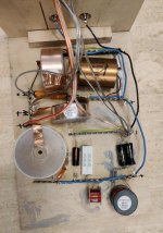
I finalized yesterday my Elsinore ULD build.
First I listened to the ULD with the old X-over while finishing the new x-over. After may be 5 hours of listening the sound opened and Ane Brun gave a private concert in my home.
Then I changed to the correct x-over and let everything play for some hours. in the evening I did some listening and encountered as follows;
I the night while sleeping I thougt about this (everynone may be aware of this penomenia). There may be 3 possible scenarios.
I am convinced that this problem will be solved next weekend (my Elsionore ply in my friends room and I am only able to visit her on weekends).
So far, if someone has some spare money and a lot of time, go for the ULD Elsinores. Highly recommended.
I finalized yesterday my Elsinore ULD build.
First I listened to the ULD with the old X-over while finishing the new x-over. After may be 5 hours of listening the sound opened and Ane Brun gave a private concert in my home.
Then I changed to the correct x-over and let everything play for some hours. in the evening I did some listening and encountered as follows;
- the Purifi drivers are worth every cent, the sound changed significantly. The bass is stronger , may be deeper, that is not so important for me, but the deep region is a lot clearer. Sometimes the Elsinores sound shlightly muddy for me, I am using the PASS V_Fet amplifier (its single ended) With the 8W Monster (push-pull) there is no more mud.
- midds are lightning fast, I had no idea that the Elsinores can be bettered that much. Tonality doesn't change that much, everything is clearer.
- highs are my problem, they don't fit to the rest. There is some irritation and longer listening lead to fatigue.
I the night while sleeping I thougt about this (everynone may be aware of this penomenia). There may be 3 possible scenarios.
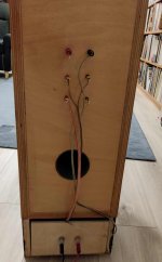
- I confused the polarity of the tweeter because I had to change the cabling during work (my cable was not long enought) and used a preasembled cable (I would give this the highest probability),
- the big C1, 1,8 µ needs time to burn in
- I have to use R1 in a different way, I have a R with shielding, in the previous Elsinore I used them without connecting the shielding to minus.
I am convinced that this problem will be solved next weekend (my Elsionore ply in my friends room and I am only able to visit her on weekends).
So far, if someone has some spare money and a lot of time, go for the ULD Elsinores. Highly recommended.
Attachments
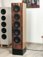
Definitely not, I use the "normal" Elsinore since one year (visible in the backgraund), no experience like this.
But the main part that is causing the increased distortion is the differences in driver impedance vs cone
position, right? And what you have found is that one can make a voltage source amplifier behave way better by using the inductor in series.
The conjugation network is there to make sure that a current amplifier will produce the same frequency curve as a voltage amplifier, right? Or
does it do more for a voltage amplifier that I did not figure out yet...
I think you are on the way to figuring this out. Keep thinking about it.... that helped me.
OK, here goes, I am going to make what I hope is a good attempt...
Yes, the position of the driver cone, assuming it is within the limits of Xmax, does not draw the same current as it does in the rest/mid position.
If the cone is in then the inductance goes up. The impedance seen by the amplifier also goes up. Current goes down.
If the cone is out then the inductance goes down. The impedance seen by the amplifier also goes up. Current goes up.
The amplifier's current is no stable.
Let's look at what the above looks like, something like this Klippel curve:
So this is 10mm peak-to-peak excursion.
Using the above, let us add a series 1mH inductor:
| Col 1. | col 2. | Col 3. | Col 4. | Col 5. |
| -5mm | 0.7mH | +49% | 1.7mH | +17& |
| 0mm | 0.47mH | 0% | 1.45mH | 0% |
| +5mm | 0.25mH | -47% | 1.25mH | -14% |
In fact the total variation from in to out is nearly 3:1 before we add something to stabilise that.
Now adding 1mH and look at columns 3 and 4 and something interesting has happened. It's gone from near -/+50% to around -/+15%
In ratio terms we have gone from 2.8:1 down to 1.35:1 and this has now stabilised the impedance.
Look below for an example of what we are trying to stabilise:
Here Red is resting. Blue is when the cone is -5mm in position and Green is +5mm out.
The impedance plot you often see in reports are not stable impedances, they are potentially dancing all over the place!
And the crossover, they can make the problem worse and also, if you are clever about it, make it better.
Now imagine a 30-50Hz bass line modulation whilst reproducing musical content containing frequencies up to the midrange - and this is not an ideal situation. I tell people "don't trust impedance plots" and they don't understand me. Change the position of the cone and the impedance is no longer the same.
NOTE 1: The current of the amplifier is modulated by the imperfect driver and you have a mechanism for more distortion.
NOTE 2: The driver cannot be improved, it is what it is. But you can find ways to limit the damage. Or make a better driver!
Solutions:
1. Purifi drivers try to produce a driver that behaves itself. This is where problems are triggered, there can be no substitute for good and better drivers.
2. Develop techniques that reduce the influence of less-than-perfect drivers on the amplifier. This is what the Elsinores do and achieve very well with high quality and extremely low inductance drivers, currently SB Acoustics SB17MFC35-08.
There are a number of techniques used that I mentioned recently, series inductors will do a lot of cleaning up the current of the amplifier, current EQ, proper application of a waveguide tweeter, and so on.
Compare the above 'Klippel' curve to this:
Now understand we can understand why the Purifi is so special. The inductance is not particularly low, but it is incredibly stable with excursion and hence impedance/current modulations are very low to start with.
Let us look at the SB Acoustics driver we use in the standard Elsinores and why they are way above average:
I have confirmed the above measurement and whilst not as good as the Purifi in flatness, they have an advantage of their own: Very low inductance!
Now add a 0.5mH inductor to both, the flat Purifi goes even a bit flatter again and the SB driver improves a whole lot.
The SB17 driver as the example below, let us add a series 0.5mH inductor.
| Col 1. | col 2. | Col 3. | Col 4. | Col 5. |
| -5mm | 0.17mH | +41% | 0.67mH | +8% |
| 0mm | 0.12mH | 0% | 0.62mH | 0% |
| +5mm | 0.95mH | -26% | 0.595mH | -4% |
Look how stable things are in columns 3 and 4 after the 0.5mH inductor is added in series. Now use four drivers in series parallel and the approx 12mm peak-to-peak excursion of that drive becomes a massive 48mm.
The effect is shown below with four drivers and since only 2.5mm p/p excursion is now required for 10,, p/p excursion, we can see that I doctored the measurement to look like below.
Compare that to the above. Now four SB17 drivers as the example below, let us add a series 0.5mH inductor.
| Col 1. | col 2. | Col 3. | Col 4. | Col 5. |
| -5mm | 0.13mH | +8% | 0.63mH | +2% |
| 0mm | 0.12mH | 0% | 0.62mH | 0% |
| +5mm | 0.11mH | -8% | 0.61mH | -2% |
Again, look at columns 3 and 4. Now the impedance will vary by only a few percent. Pretty amazing!
I am not sure how you guys reading the above understand that we are trying to eliminate distortion due to the driver not having a stable impedance and hence impedance/current modulations are the result, and how this leads to additional distortion.
We cannot reduce the distortion of the speaker, but we can use techniques that reduce the distortion of the amplifier because as a voltage source it cannot control current, only voltage.
So I will leave it there. It's up to you guys whether you want to understand this or not - but at least it will give Elsinore builders some idea of what is behind the thinking of the design.
Cheers, Joe
Attachments
I am convinced that this problem will be solved next weekend (my Elsionore ply in my friends room and I am only able to visit her on weekends).
So far, if someone has some spare money and a lot of time, go for the ULD Elsinores. Highly recommended.
Check the wiring and all the crossover components, or even better, get somebody else to do it. Sounds like you have others around.
Last edited:
Thanks for the write-up, Joe.
This was very clear to follow. I take it that the current EQ helps us to get the same results no matter which amplifier is used?
Or does it have another function besides letting the amplifier "see" a resistor like impedance plot.
This was very clear to follow. I take it that the current EQ helps us to get the same results no matter which amplifier is used?
Or does it have another function besides letting the amplifier "see" a resistor like impedance plot.
Hey Joe,An update to Hamlets and another surprise.
I have been dollying up my own Elsinores which date back to Mk2 circa and hence need the old square fill-in for the waveguide. I will post photo some time soon, but what I used was Duratex roll-on textured finish.
Duratex Video
I have bought the MFC drivers for the Hamlets, they are here now. The new drivers will be fitted and the box will be given the Duratex treatment. Within a matter of weeks will be doing the computer modeling and get the crossover worked out. It will be the same crossover as I used with the earlier HDS drivers, but there is expected to be between 3-5 changes in values, the topology will be exactly the same.
Now for a little surprise, take a look at this photo:
An externally hosted image should be here but it was not working when we last tested it.[/URL]
Dayton B452-AIR
Now as it is, it is cheap and great for a computer speaker. But I am going to take it much further and I will publish the details so that this will be a great little satellite speaker.
I will let you in on the first step that I have already done. The AMT tweeter is of course, the attraction here, but it uses a cheap (only so-so OK) polypropylene mid-bass driver... so we replace it with this:
An externally hosted image should be here but it was not working when we last tested it.[/URL]
IMPORTANT: Must be the 8 Ohm version as shown - Dayton PC105-8
Just replace with this much better driver, BUT it is not a straight fit, you will need to file away not quite a millimeter where the four holes are, as it is a slightly larger driver. The existing mounting holes are just fine.
Later, we shall develop this into something more advanced and take advantage of the drivers that are now both of them good, and not just the AMT tweeter.
Use it like that for now, it is amazing value and we shall make it better still after I have done some measurements etc.
4" FULL RANGE POLY CONE DRIVER - DAYTON AUDIO
SMOOTH RESPONSE WITH TRUE FULL-RANGE REPRODUCTION
Dayton Audio’s PC105 4” full-range driver will deliver smooth and natural response from extremely compact designs. When used in line arrays, portable speakers, sound bars, or as a dedicated midrange in 3-way designs this driver will prove to be an excellent value.
Poly damped woven glass fibre cone controls cone break-up and provides a smooth roll-off
Copper cap keeps inductance under control and extends high frequency response
1" vented aluminium voice coil former and vented pole piece for high power handling
High energy ferrite magnet increases BL for higher efficiency and more output
Smooth response with true full-range reproduction for simple speaker designs.
The current discussion regarding adding series inductors to flatten the impedance curve is very interesting - unfortunately my background is medical rather than electrical so the background theory is hard for me to follow, but the addition idea of reducing the % variation by adding external inductors that are much larger than the variation makes sense to me. Obviously you’ve used that in the elsinores to great effect - I am enjoying my ULD elsinores immensely (I added the 33R resistor to each cover yesterday, although did not swap the RC values yet).
You may or may not remember but im using the above mentioned Dayton 452s with the replaced bottom driver you had mentioned before in the above post. From memory, the bottom full range driver has no xover components in series with it - there is just a high pass to the tweeter and and then the larger driver directly driven from the input signal. I am thinking that perhaps one way to improve this design would be to add a series inductor before the larger driver in order reduce the impedance variations as discussed above? Does this often change the frequency response of the driver enough to require other changes? I apologize for my ignorance but thought I’d ask, as I do have some nice jantzen 0.33mH inductors laying around after the switch from my mark V elsinores to the ULD ones.. the voice coil inductance on the PC105-8 drivers you suggested is 0.54mH (was 0.41mH on the peerless HDS drivers that these inductors were used with - however those were 2 in series so 0.82mH behind the inductor)..
Anyways, sorry - just was hoping to be able to do a quick upgrade on those speakers with parts I already have on hand! Thanks a lot!
https://www.parts-express.com/Dayto...MImZjc2r3a-QIV0MmUCR2lmAZEEAAYASAAEgIKafD_BwE
https://www.parts-express.com/Peerless-830875-6-1-2-Nomex-Cone-HDS-Woofer-264-1092
Hello All,
I went looking on my desktop and found this QA impedance and phase plot for the ScanSpeak XT25 tweeters that are installed in sealed boxes with HDS830875 woofers on my workbench. The same tweeters discussed back in the early posts of this thread.
As installed and measured the tweeters have 4 Ohm Mills resistors installed in series.
Both the impedance plot and phase plot are much flatter with the the 4R Mills resistor in series.
Thanks DT
Thanks for the write-up, Joe.
This was very clear to follow. I take it that the current EQ helps us to get the same results no matter which amplifier is used?
Or does it have another function besides letting the amplifier "see" a resistor like impedance plot.
I hope you realise quite a bit of effort was required for that post, so it is gratifying to me that you are understanding the concepts because it means if others read and try to understand it, they will. But it takes a bit of mental effort.
I want the world to become more aware that the imperfect driver causes the amplifier to produce "current distortion" due to what Esa Merilainen has called "EMF-derived distortion."
The beauty is that we can measure this distortion!
Note that the above measures the amplifier's "current distortion" and not that of the speaker, even if it is "EMF-derived distortion."
Yes, the amplier is what we are testing. Indeed with the same driver and changing the amplifier, we may well find that the two amplifier design might well produce somewhat different distortion profiles. Wouldn't that be cool, because we are measuring the distortion of the amplifier and finding differences? The implications are enormous: Amlifers do sound different and we can measure them/why?
That thought is not that easy to grasp. Use a high-quality audio analyser to measure the distortion in the above jig. This is set up for 8 Ohm driver, but change the gain = 30 approx, and then it is set up for 4 Ohm drivers. This way you recover the voltage that appears across the DC resistance of the voice coil as the suitable voltage that is proportional to the current that produces the force factor.
Acquired this 32bit analyser below, very lucky to get it as only few were availble due to chip shortage:
So we can see, and I know that I am repeating myself, that we cannot improve the driver itself, we have to start with a good driver to start with. That means looking at the impedance plot and looking for two things. 1) The lowest possible inductance and here the SB Acoustics SB17 drivers excel. 2) The flattest possible impedance change with any movement/excursion of the driver and here the Purifi drivers excel. You need at least one of them, but I doubt if it is possible to get both.
SB17MFC35-08:
PURIFI:
Now that is still reasonably low inductance compared to others, around double. But in this case it is not bad because the inductance is flat with any excursion and that is reveled here:
That aspect is much superior to the SB17 driver. You can see that the Purifi inductance is about twice, but much flatter with respect to voice coil position. The SB17 has ultra-low inductance, but not as flat. You can have one or the other, but unlikely both.
I take it that the current EQ helps us to get the same results no matter which amplifier is used?
Or does it have another function besides letting the amplifier "see" a resistor like impedance plot.
Very good question and indeed the logical next step to understand. Give me a quiet moment and I will post something about that.
But even now it must occur that the answer is yes and for one simple reason: If you have a significant change in inductance with excursion at the crossover frequency, can you see that the low pass filter frequency is not stable? That can't be good. I am thinking that the majority of the most common two-way speaker designs are LR4 crossovers, and although I have suspicions about this and the unstable (you cannot trust) impedance of the driver when it is in the rest position, what effect does that have on high-order crossovers. Maybe sometime in the future, somebody capable will do some research into this. What I am hearing in LR4 crossovers, is a kind of dullness that you only hear when it's not there, and there has to be a reason. My fellow Dane, Troels Gravesen has gravitated toward low and first-order design (and waveguides too, he has tested mine as used in the Elsinores). He is hearing something and I know what it is, because so am I. But do we have clues? Yes, I believe we do and they are more answers on the electrical side than on the acoustic side, IMO.
Get back to you...
Both the impedance plot and phase plot are much flatter with the the 4R Mills resistor in series.
Thanks DT
Indeed they are! But using any series impedance like that intelligently and by design, can be used to reduce distortion on the current side.
But there is a trade-off that must always be kept in mind.
It will improve 'control' of the current at the expense of having less control over the voltage.
Hey Joe,
... the addition idea of reducing the % variation by adding external inductors that are much larger than the variation makes sense to me. Obviously you’ve used that in the elsinores to great effect - I am enjoying my ULD elsinores immensely (I added the 33R resistor to each cover yesterday, although did not swap the RC values yet).
You may or may not remember but im using the above mentioned Dayton 452s with the replaced bottom driver you had mentioned before in the above post. From memory, the bottom full range driver has no xover components in series with it...
You raise a number of things. Yes there are designs about there where the driver has no low-pass filter, sometimes the driver is designed exactly for that purpose. I can't really comment too much, and while adding an inductor and lower distortion, it might also upset the crossover point. Typically you could end up with a suckout in the upper mid or lower treble area. If you have a way to measure the response and add the 0.33mH inductance and see what happens, then it might be worth playing around with it. But beyond that, I can't say too much.
Addition to my yesterday post: Problem is fixed, it was the easiest thing ever, I confused the polarity of the tweeter.
Now everthing is like it should be and sounds as I hopped it would do. Or even a lot better.
It's like some guys allways write , go and build something, preferably a set of Elsinores ULD. Guess this is the end of my long journey for the best speakers.
Now everthing is like it should be and sounds as I hopped it would do. Or even a lot better.
It's like some guys allways write , go and build something, preferably a set of Elsinores ULD. Guess this is the end of my long journey for the best speakers.
- Home
- Loudspeakers
- Multi-Way
- The "Elsinore Project" Thread