You funny guy's .... 😀
Actually, the only thing missing on my PCB, is the 10uF cap's at output, and the following resistors : R6/R7 R18/R21, they form the gain of the circuit right... so if i want a lot of gain i have to set them to 15K / 6K to give me 25x gain, am i right ???
Jesper.
Actually, the only thing missing on my PCB, is the 10uF cap's at output, and the following resistors : R6/R7 R18/R21, they form the gain of the circuit right... so if i want a lot of gain i have to set them to 15K / 6K to give me 25x gain, am i right ???
Jesper.
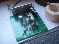
Attachments
Well, one reason would be that by keeping it stock till it's working, you can compare notes with the rest of us 😉
Another reason would be that it could make it possible to figure what's wrong with your gain issues, if you had a pre that wasn't 247dB gain😀
Magura 🙂
Another reason would be that it could make it possible to figure what's wrong with your gain issues, if you had a pre that wasn't 247dB gain😀
Magura 🙂
well Morten... I am pretty sure, it's not the problem, but could you perhaps just tell me, if i can increase the gain or not ?
Jesper.
Jesper.
lykkedk said:well Morten... I am pretty sure, it's not the problem, but could you perhaps just tell me, if i can increase the gain or not ?
Jesper.
Sure you can 🙂
Magura 🙂
lykkedk said:well Morten... I am pretty sure, it's not the problem, but could you perhaps just tell me, if i can increase the gain or not ?
Jesper.
Magura said:
Sure you can 🙂
Magura 🙂
yup ......... at least to 3256 db ............

From ZenMooo minicookbook.
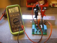
Sucess... well it was no problem making theese adjustment's, i had set R25 to MAX, and then lowered the resistance down, to have ~3,3vdc across R24... (voltage was going from 2,1vdc - 3,3vdc when adjusting).
I found ~1,21 and 1,24 vdc across R1/R17, without adjusting at all.
The Q1/Q6 get's pretty hot, realatively fast... how much will they dissapate ? Are they supposed to get hot (do i need big sinking?) Also Q7/Q8 get's warm, but nothing special.
I heard some circuitsinging, during R25 adjustment's, i guess it's some choke-song or like 😀 ... Not comming from choke itself, but from circuit, which i found a bit strange.
I donno when i can find the time, to make further progress... but it look's like the thing is working... and that's good !
Jesper.
set R25 to max value
set both R5 and R11 to mid point (value ) if they aren't already
then ( after powering up) - adjust R25 to have 15 mA through center CCS , or 3V3 across R24
then set R5 to have 1V to 1V5 across R1
then set R11 to have same voltage across R17 , or - BETTER - to have 0V between drains of Q1 and Q6
all inputs grounded
Sucess... well it was no problem making theese adjustment's, i had set R25 to MAX, and then lowered the resistance down, to have ~3,3vdc across R24... (voltage was going from 2,1vdc - 3,3vdc when adjusting).
I found ~1,21 and 1,24 vdc across R1/R17, without adjusting at all.
The Q1/Q6 get's pretty hot, realatively fast... how much will they dissapate ? Are they supposed to get hot (do i need big sinking?) Also Q7/Q8 get's warm, but nothing special.
I heard some circuitsinging, during R25 adjustment's, i guess it's some choke-song or like 😀 ... Not comming from choke itself, but from circuit, which i found a bit strange.
I donno when i can find the time, to make further progress... but it look's like the thing is working... and that's good !
Jesper.
Attachments
Hmm... dosen't look to good, my first test with a testtone, gave me some crazy high oscillation/whatever, not even readable on scobe thing's. The singing from circuit, is real hard to locate, but maybe it's a cap or one/both irf9610, but nomatter, when i figure out howto fix this, this singing is not something which is very good.
Right now, i have no clue where to start.
Jesper.
Right now, i have no clue where to start.
Jesper.
lykkedk said:Hmm... dosen't look to good, my first test with a testtone, gave me some crazy high oscillation/whatever, not even readable on scobe thing's. The singing from circuit, is real hard to locate, but maybe it's a cap or one/both irf9610, but nomatter, when i figure out howto fix this, this singing is not something which is very good.
Right now, i have no clue where to start.
Jesper.
did you make it with 10k/100K feedback net ?
are choke halves in phase ?
did you make it with 10k/100K feedback net ?
are choke halves in phase ?
I will change the feedback net, to 10k/100k, but what do you mean choke halves in phase ?
Jesper.
lykkedk said:
I will change the feedback net, to 10k/100k, but what do you mean choke halves in phase ?
Jesper.
Attachments
I just sent off Lykke with a few instructions and a heatsink, so with a little luck, things will be sorted out within the next couple of days 😎
Magura 🙂
Magura 🙂
Magura said:I just sent off Lykke with a few instructions and a heatsink, so with a little luck, things will be sorted out within the next couple of days 😎
Magura 🙂
correct me if I'm wrong - your's drek was fully functional in proto?
have you any clue what's wrong with Lykkkkk's ?
Zen Mod said:
correct me if I'm wrong - your's drek was fully functional in proto?
have you any clue what's wrong with Lykkkkk's ?
The proto was closer to a BOSOZ than a drek.....
A few things could be wrong.
1) Wrong calc of gain setting resistors.
2) Temp drift on very small heatsink.
3) Not zeroed well enough.
4) Inductors out of phase.
5) Noise picked up by inductors.
I will talk it over with Lykke again later, now he is going to start out by setting gain back to 12, mount a respectable heatsink, zero it out better, and check the inductors are in phase.
Magura 🙂
I will talk it over with Lykke again later, now he is going to start out by setting gain back to 12, mount a respectable heatsink, zero it out better, and check the inductors are in phase.
And that was the key, for having a functional DREK ... 😀
 ... Well i lowered the gain back to 100K/10K, and setup the coil, as in ZenMod's suggestion, and everything is working now.
 More to come...
Jesper.
lykkedk said:
And that was the key, for having a functional DREK ... 😀
More to come...
Jesper.
now - don't be shy ( I presume that you finished the dishes for today 😉 .....) - tell me how drek farting , comparing to uberdrek you already have ......

now - don't be shy ( I presume that you finished the dishes for today .....) - tell me how drek farting , comparing to uberdrek you already have ......
Geee... i kindof know this was comming from you now... - sry. will be some time, till i can tell. maybee this weekend in mono i don't know!
Perhap's you can tell me, how much voltage this heating monster can swing ??? - will it be capable of 25xgainsetting as UberDrek

Will it drive my F4 (thihihi...)
Jesper.
lykkedk said:
Geee... i kindof know this was comming from you now... - sry. will be some time, till i can tell. maybee this weekend in mono i don't know!
Perhap's you can tell me, how much voltage this heating monster can swing ??? - will it be capable of 25xgainsetting as UberDrek
Will it drive my F4 (thihihi...)
Jesper.
same........... I already knew that you'll be gain-greedy .......
lemme tell ya :
with 95db/W/m spks you have , with decent source ( not MC head ) , with (preamp - drek or uberdrek,whatever) gain setting of 10-15 x (so - between 20 and 24 db) and with two F4 you also have - you'll launch your funny danske back side through window ........
if that is not the case , something is seriously wrong , and I have no slightest clue what is in question
- Status
- Not open for further replies.
- Home
- Amplifiers
- Pass Labs
- The Drek builder's thread