I use 6.8v with 4.7kThat is definitely one approach that will work.
If you have 25 turn pots and using a 6.2V Zener, then I would set both pots to centre or you will be bloody turning forever. Hahaha
What Zeners are you using
If you have the luxury of 4 test meters so as to get the F6 upto temp and even bias and offset this is the best way to do it.🙂
.jpg")
In that case set both to centre
Thanks
Chassis is almost ready but still have to wait for the transformers. Will post result after.
If you have the luxury of 4 test meters so as to get the F6 upto temp and even bias and offset this is the best way to do it.🙂
View attachment 510746
I only have two.

OK I have my transformers finally and I start stuffing the board at the moment. I have the following parts in 1/8watt RN 55. Could I use them in this amp, or I have to go with 1/4 Watt.
R6 47 k, R 9&10 10K and R11&12 100 R.
Thanks
R6 47 k, R 9&10 10K and R11&12 100 R.
Thanks
RN55 is a mil-spec resistor with 100% derating. I.E., it's really a 1/4w resistor that says 1/8w on the spec sheet.
Use them, they're great!
Use them, they're great!
Perhaps this has been asked somewhere in the myriad F6 threads, but...
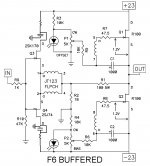
Has anyone tried to build the F6 with some resistance between the drain of the bottom FET and output? I compared a SPICE simulation of the F6 with 0.47-ohm source resistors to the same circuit with 0.235-ohm added between the drain of the bottom FET and output/0.47-ohm source resistor of top FET and the (simulated) distortion dropped by a startlingly large number. The harmonic profile also changed to be more 'pleasingly' 2nd-harmonic dominated.
Has anyone tried to build the F6 with some resistance between the drain of the bottom FET and output? I compared a SPICE simulation of the F6 with 0.47-ohm source resistors to the same circuit with 0.235-ohm added between the drain of the bottom FET and output/0.47-ohm source resistor of top FET and the (simulated) distortion dropped by a startlingly large number. The harmonic profile also changed to be more 'pleasingly' 2nd-harmonic dominated.
I'm getting cancellation of 2nd Harmonic but 3rd Harmonic is staying the same.Perhaps this has been asked somewhere in the myriad F6 threads, but...
Has anyone tried to build the F6 with some resistance between the drain of the bottom FET and output? I compared a SPICE simulation of the F6 with 0.47-ohm source resistors to the same circuit with 0.235-ohm added between the drain of the bottom FET and output/0.47-ohm source resistor of top FET and the (simulated) distortion dropped by a startlingly large number. The harmonic profile also changed to be more 'pleasingly' 2nd-harmonic dominated.
hrks, i just came across the hint 6L6 and generg gave earlier, just to feed the amp with a 1000 Hz signal (from i pod) and, across a 4-8Ohm Loadresistor go to the computer. The Software i used is Sine Scope.
totally uncalibrated, i just made a bit louder to see anything. looks quite bad doesent it? Don´t know if its the amp or a fault in measuring.
Maybe the ones who did this, could you share some settings.
tnx
st.
totally uncalibrated, i just made a bit louder to see anything. looks quite bad doesent it? Don´t know if its the amp or a fault in measuring.
Maybe the ones who did this, could you share some settings.
tnx
st.
An externally hosted image should be here but it was not working when we last tested it.
as for the input plug, i just cut off an ol´headphone, stereoplug and one channel just cutted away... ill buy a mono plug soon.
That looks like a poor signal generator more than anything else.
Build this probe to attach across the load resistor - Electronic Equiptment - DIY soundcard scope probe
Build this probe to attach across the load resistor - Electronic Equiptment - DIY soundcard scope probe
Also make sure you not overloading your card input. The output voltage most likely needs to be stepped down
I'm getting cancellation of 2nd Harmonic but 3rd Harmonic is staying the same.
Perhaps I spoke too soon. I noticed the improvement with my (rough) Cree C3M spice model. The effect with IRFP240 seems to be to raise overall distortion slightly.
Sorry. Disregard for now.
Hello!
Just built myself an F6 amp! everything works very well, no magic smoke and everything went very smoothly.
However the bass quantity (not quality) is a bit weak, kinda sounds like "puff" instead of "omph" when some electronic bass transient are playing.
I had the same thing happen with the F5 i built, so i'm starting to think that this type of amplifier is not right for the speakers i have (Focal electra 1028Be) They are quite efficient at 90-91db/w and nominal 8 ohm.
When i use some 200W/ch@8ohm amp there is quite a lot more bottom end speed and "omph" but the mid and HF on the F6 is for sure better and it images a lot better too.
Anyone having experience with this kind of setup?
EDIT: Because i have some matched pairs of the 2sk1530/2sj201 combo i used them in both project (2xK1530 in F6 ofc.) But doubt they are to blame for low bass quantity
EDIT2: Was thinking it might be possible to throw in another output pair and up the supply voltage a bit, to say +-32V but that would put the input JFETs at risk so was wondering if it might be possible to use a slightly modified circuit as to my superb windows paint drawing 😉
Using resistor in modified circuit, but of course one could use some more exotic, like a voltage regulator here, this keeping the input JFETs at say +-22-23v.
Attachments
Last edited:
What sort of powersupply are you using?
That is what VA rating on transformer and how much capacitance in power supply?
That is what VA rating on transformer and how much capacitance in power supply?
- Home
- Amplifiers
- Pass Labs
- The diyAudio Firstwatt F6