75W
forced
prayer
forced
cooling
50W
no
prayer
no
forced
How did Nelson achieve 75W in Zen 5?
brute force approach , what else ?
he's always having few hundred-kilos of Al around ........ and few fans
remember bucket cooled toobz , HAM world ?
so , nothing new under the sun
he's always having few hundred-kilos of Al around ........ and few fans
remember bucket cooled toobz , HAM world ?
so , nothing new under the sun
I've got 10000 litres of liquid nitrogen at work.
I wonder how long that would last. Hahahaha
I wonder how long that would last. Hahahaha
Not sure how trustworthy simulation is but after tweaking the circuit I get this:
THD at 1Wrms into 8 Ohms 0.058%
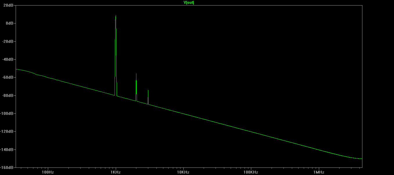
Quite plausible result in real life too.
I've had a while to listen to mine at this point and I am very pleased with the results. To me the most impressive aspects would be the amazingly coherent soundstage and simply a pleasant sound, perhaps a result of the abundant 2nd harmonic. I'm sure the transformer plays big role in there as well.. The bass is thick and full while the treble shimmers.
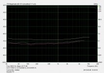
Also I made some distortion measurements. I don't have any professional equipment; I just used my PC along with Arta's audio analysis software. Anyways these were my results at about 25W (14V@8ohms)
Also I made some distortion measurements. I don't have any professional equipment; I just used my PC along with Arta's audio analysis software. Anyways these were my results at about 25W (14V@8ohms)
Attachments
Last edited:
Can you do it at 1W.
Lower power distortion interests me more.
I'm waiting on a new distortion analyzer to arrive so have no way of measuring it at the moment.
Lower power distortion interests me more.
I'm waiting on a new distortion analyzer to arrive so have no way of measuring it at the moment.
I'm getting quite a different output impedance result (simulation) than published can someone else check it.
I'm not sure if I'm doing something wrong.
I'm not sure if I'm doing something wrong.
If you can measure the space that would be great.
I had a chance to photo them, these are 18.2 mm in diameter, 1000uF 35 volt Elma Silmic:
pretty much fit perfect. looks like your are 50 volt, but diameter appears the same. Just covers the silk layout circle.
Attachments
![IMG_4131[1].jpg](/community/data/attachments/468/468334-97d013e32b9f54544cbcdea60a8db063.jpg?hash=l9AT4yufVF)
![IMG_4130[1].jpg](/community/data/attachments/468/468354-02df0b5656dd9eb5153ef402d758ba11.jpg?hash=At8LVlbdnr)
Last edited:
I had a chance to photo them, these are 18.2 mm in diameter, 1000uF 35 volt Elma Silmic:
pretty much fit perfect. looks like your are 50 volt, but diameter appears the same. Just covers the silk layout circle.
No problems on that board, but the other board is a different story as you know the 2 boards are different.
As I stated before, if you're trying to use a 18mm cap for C2 on the other board, there isn't enough space between R2 and R10 according to my trusty ole' Starrett calipers.
R10 can easily be relocated on the bottom of the board.
Also, I would shift R2 and R3(before soldering them in place) away from C2 until there is some space between R2 and C2.
Russell, what's up with those "monster" Dale resistors for R11 and R12?🙂
Just found this 4 turn pot. https://www.digikey.com.au/product-detail/en/3339H-1-502LF/3339H-502LF-ND/1088285
Anyone used them?
I've been looking for something like this for a long time. 1 turn is not enough and 20 turns is way too much.
Anyone used them?
I've been looking for something like this for a long time. 1 turn is not enough and 20 turns is way too much.

3339P has the right pinout geometry for the F6 pcb (not 3339h)
https://www.digikey.com.au/product-detail/en/3339P-1-502LF/3339P-502LF-ND/1088297
https://www.digikey.com.au/product-detail/en/3339P-1-502LF/3339P-502LF-ND/1088297
I fall in the patience camp to, I like plenty of turns before things change too much, just my personal preference.🙂 The Bourns pots I used have about 25 turns. This one (or whatever value is needed):
3299W-1-102LF Bourns Inc. | 3299W-102LF-ND | DigiKey
Russellc
3299W-1-102LF Bourns Inc. | 3299W-102LF-ND | DigiKey
Russellc
Gonna go with Vishay BC PR03 with copper leads for feedback resistors. Never used them before but they look of decent quality equal to Panasonic or possibly a touch better (at least on paper).
Is is best to put 2 x 200Ohm in parallel
http://www.digikey.com.au/scripts/DkSearch/dksus.dll?Detail&itemSeq=179744027&uq=635776005415073842
Is is best to put 2 x 200Ohm in parallel
http://www.digikey.com.au/scripts/DkSearch/dksus.dll?Detail&itemSeq=179744027&uq=635776005415073842
No problems on that board, but the other board is a different story as you know the 2 boards are different.
As I stated before, if you're trying to use a 18mm cap for C2 on the other board, there isn't enough space between R2 and R10 according to my trusty ole' Starrett calipers.
R10 can easily be relocated on the bottom of the board.
Also, I would shift R2 and R3(before soldering them in place) away from C2 until there is some space between R2 and C2.
Russell, what's up with those "monster" Dale resistors for R11 and R12?🙂
For the correct value at time of order, that was what was available in Dale, I think they are 1/2 watt, just stood them up soldier style!
Well, semi reclining soldier style.
As to the boards, I was under impression that 2picodumbs was using store board.
Russellc
Last edited:
- Home
- Amplifiers
- Pass Labs
- The diyAudio Firstwatt F6