When I was building my J I broke one of the leads of my spencer supplied jfets. I replaced the pair with DIY store jfets. I can't hear any difference. Could be my hearing
... missing only the wiring!
Inform me if there is a demand for the PCB: 70µm, white soldermask (no silkscreen, I hate this font!), 359x80mm
A pity that the VFET are no longer available!
Nice challenge the PCB for the VFET Part2...
Inform me if there is a demand for the PCB: 70µm, white soldermask (no silkscreen, I hate this font!), 359x80mm
A pity that the VFET are no longer available!
Nice challenge the PCB for the VFET Part2...
Attachments
After a quick blessing from our technical, spiritual, and menu advisor, Nelson Pass, I am glad to present the preliminary discution for the diyAudio Mosfet F6.
Cool, huh? 🙂 This is made for IRFP420, or a similar Mosfet that has a Vgs in the 4V range. This is a beautifully simple amplifier!
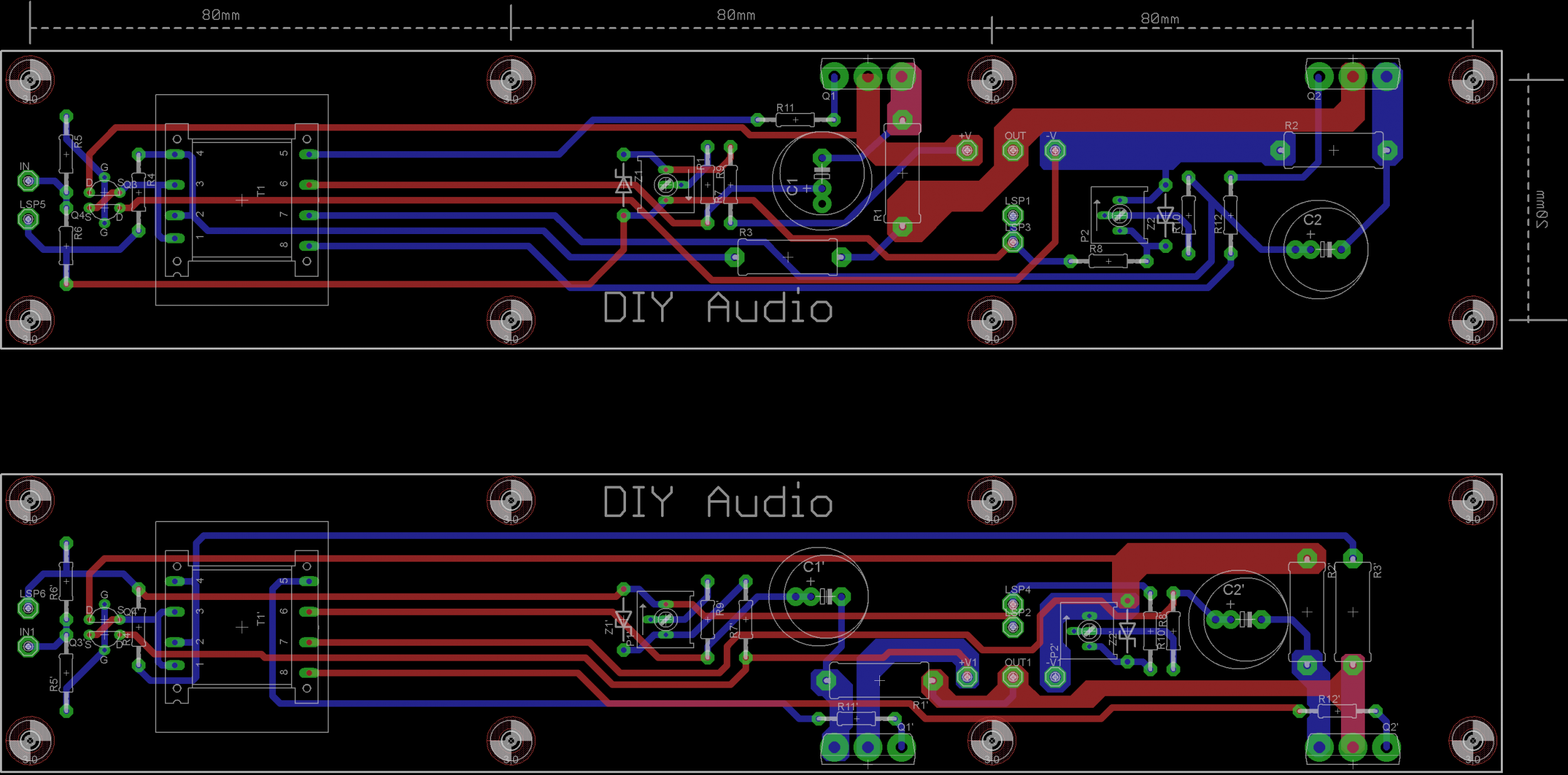
Member Didiet78 has done some preliminary layout, (Thanks a million! It looks wonderful!!) this is the current thinking - 2 PCB, a left and a right, in order to keep the input transformer as far back as possible on both sides, and to have the Mosfet mounted low on the heatsink. The PCB will be designed to only mount the specified Jensen transformer, but I'll look into the possibility of a second set of pads, if possible, to mount a Lundhal or something... No promises.
The diyAudio store is also looking into stocking the transformers, which would make the whole process quite easy.
The other consideration in this project is the PSU, by which a shielded transformer is going to be very necessary, mounted as far from the input transformer as possible, and possible in a screening can as well. Or, of course, a separate box for transformer, diodes and first capacitor bank. Other than that, everything is straightforward. The diode, cap and resistor bank are the 'Firstwatt vernacular', I.E., look at any Firstwatt amp and use that PSU. The diyAudio PSUv3 boards will work beautifully, as will many other PCB.
The floor is open for discussion. 😀
I just bought a stack of these Elna Capacitors
http://www.digikey.com/product-search/en?mpart=RFS-50V102MK9%235&vendor=604
The diameter is 18mm. Please tell me there is room for them to fit on the PCB.
Please allow for these caps. There are no substitute in my opinion.
Last edited:
the 1000µ has a diameter of 18mm and a pitch of 7.5mm (standard value, 10mm pitch should be nice but hard to obtain).
The resistors are type PR9372 1/2W (made in USA! no, why? I´n not in marketing! I will say a tribute to Mr. Pass?!).
The power resistor from MILLS or CADDOCK (also USA!).
Cermet Potentiometer (best one from VISHAY take a look at the Kaneda preamplifier article from Mr. Hiraga, sorry he is french!).
You can replace the CRC by wiring CLC (faston connectors supplied).
I use one 47000µ capacitor instead of 3x 10000µ for cost reasons (MUNDORF Germany supplies nice types).
PCB is constraints (primary AC to DC and PE) checked (used german VDE norm).
The routing is duplicated on top and bottom side = 140µm copper!
Attachments
I just bought a stack of these Elna Capacitors
http://www.digikey.com/product-search/en?mpart=RFS-50V102MK9%235&vendor=604
The diameter is 18mm. Please tell me there is room for them to fit on the PCB.
Please allow for these caps. There are no substitute in my opinion.
I'll have to check, but I do believe that is the very one I put on my F-6 boards.
Russellc
@ JPS1964
I admire your interesting work 🙂
See some Caddocks source resistors and think about no inductive version serie:
http://www.mouser.com/ds/2/62/MP800_Series-2189.pdf
Caddock caddock 1k ohm Passive Components | Mouser
Mills wire wound are other candidates too

I admire your interesting work 🙂
See some Caddocks source resistors and think about no inductive version serie:
http://www.mouser.com/ds/2/62/MP800_Series-2189.pdf
Caddock caddock 1k ohm Passive Components | Mouser
Mills wire wound are other candidates too
The WTF moment as I had explained was the 20 sec or so delay to bias up. Failed analysis means parts do not meet specification when tested.
As for the reason for replacing the parts, when the F6 combo was purchased the diy store jfets were out of stock.
Given that I found the amp with the Spencer supplied parts initially without a reduction in feed back somewhat lacking in dynamics and having some concerns regarding the appearance of these parts, when the store fets were back in stock I purchased them.
Now with the diy store jfets and feed back resistor values restored closer to original I am more than happy with the performance.
It has been previously posted that the amp sounds the same with either the Toshiba or Linear Systems jfets, given my findings it would seem to lend some weight that there is some issue with my Toshiba parts.
The seller has now responded requesting the return of the parts for testing, they will be photographed, Idss recorded and the parts returned as requested to the seller.
asx
The WTF moment as I had explained was the 20 sec or so delay to bias up. Failed analysis means parts do not meet specification when tested.
As for the reason for replacing the parts, when the F6 combo was purchased the diy store jfets were out of stock.
Given that I found the amp with the Spencer supplied parts initially without a reduction in feed back somewhat lacking in dynamics and having some concerns regarding the appearance of these parts, when the store fets were back in stock I purchased them.
Now with the diy store jfets and feed back resistor values restored closer to original I am more than happy with the performance.
It has been previously posted that the amp sounds the same with either the Toshiba or Linear Systems jfets, given my findings it would seem to lend some weight that there is some issue with my Toshiba parts.
The seller has now responded requesting the return of the parts for testing, they will be photographed, Idss recorded and the parts returned as requested to the seller.
asx
Is the 20 second delay not due to the capacitors as described by Nelson in his article.
Well yesterday I replaced the input transistors in my F6 that were purchased from Spencer @ fetaudio.com with the diy store Linear Systems Jfets and was stunned at the transformation of the amp, better sound staging, nice shimmer on cymbals, I could go on....
The Spencer supplied parts 2sk170 and 2sj74 failed analysis, I have raised the matter with him although he has failed to respond, the matter has now been raised with PayPal seeking refund.
That much of a change in sound certainly sounds like a classic example of psychoacoustics where you're expecting to hear a difference.
All the K170/J74s I received from Spencer were the real deal. Did you check yours with a curve tracer?
I'll have to check, but I do believe that is the very one I put on my F-6 boards.
Russellc
If you can measure the space that would be great.
Is the 20 second delay not due to the capacitors as described by Nelson in his article.
Yes, the 1000uF and 10k (plus the pot resistance) give at least a 10S time constant,
so you need about a minute to get close to the final value.
Last edited:
If you can measure the space that would be great.
I just did some measuring on one of my unpopulated boards.
I think a 18mm o.d. cap will fit without issues on the board for C1.
C2 is a different story as the cap will(or should be) be on top of R10.
I would mount R10 on the bottom of the board and I think you'll be fine.
The outside edge of the cap may be touch R10's top pad, but with the plastic sleeve around the cap I don't see that being a problem.
Yes thanks for the tip. I'll mount the resistor on the underside.
Yes thanks for the tip. I'll mount the resistor on the underside.
You're quite welcome...glad to help.
If necessary, I'll wrap the cap in plumber's teflon tape to insulate from pads
I think you'll be fine with the SILMIC II capacitors that come highly recommended by Mr. Pass.🙂
I'll be using using Panasonic 1000uF 35V caps when I assemble my F6.
you can DIY them , either air core (Lalena online calculator , go for no less than 2.2mH,no more than 0R33 Rdc ........ or EI core
if you want , I have recipe for killer EI chokes of 8-9mH
This is a lot of tedious turning
Inductance2.21 mH DC Resistance0.27 Ohms Wire Gauge14 AWG Wire Diameter64.1 mils (1 mil = .001 in) Coil Length1 in Coil Inner Diameter1 in Coil Outer Diameter2.92 in Average Turn Diameter1.84 in Wire Length105.74 feet Copper Weight1.31 pounds Turns220 Levels14.1 Turns/Level15.6
Do you have any tips to do it quickly?
...........some data for my chokes (presumably 9mH, certainly 0E2 Rdc) :
EI72 package
height of package ~30mm
entire window filled with 1,25 enameled wire
air gap ~ 0,5 mm
EI72 package
height of package ~30mm
entire window filled with 1,25 enameled wire
air gap ~ 0,5 mm
That much of a change in sound certainly sounds like a classic example of psychoacoustics where you're expecting to hear a difference.
All the K170/J74s I received from Spencer were the real deal. Did you check yours with a curve tracer?
No curve tracer, I find soundscape differences quite easy to discern, I can forgive an amp a number of shortcomings however if it cannot cast a 3D image so much of the enjoyment to be had is missing for me.
I would hazard a guess less than .5% of the general public have ever experienced that from a home HiFi system and are I suspect quite content without 3D imaging, sometimes I wish I was hehe. It was the imaging reports that steered me towards the F6, got to hand it to Nelson for this one 🙂
asx
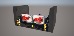
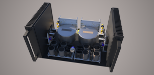
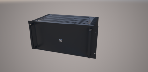
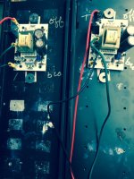
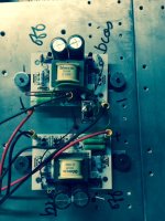
Next set of F6s ready to be cased
First is Tea Bag boards ( showing both channels) with IRFP 150s biased at 1.5A
Second shows 1 channel - 2 Tea Bag boards per channel with IRFP 240s at 1.5A. Switch allows be to change from bridge mode to SUSY mode ala buzzforbs Funny mod.
This completes my set for now. Previously showed Funny version with SS R100s at 1A on buzzforb boards.
Looking forward to comparing
Also open to evaluating other FETs
Need to put together my PSU for VFET2 this weekend
Best
Bob
Attachments
- Home
- Amplifiers
- Pass Labs
- The diyAudio Firstwatt F6