easy harry...
i'm sure hp made an honest mistake. 😛
i could have sworn that i've seen this topology before from borberly, but i could be mistaken too. in any case, i really, really like it. it is an opamp, no? i wonder what the open loop gain is. he has similar modules configured as opamps with specified open loop gain of 76dB, but they could be different. the distortion specs were absolutely outstanding however.
let's build it! i'm assumming you are referring to the complementary DC-coupled one. i'm sure the SE one is good too but i'd like to try the other one first since it conforms to my original design spec (DC coupling). i will need to order parts for it though, so you will no doubt beat me to the punch...
is anyone else as excited as i am? ok i guess this is no big deal since it's just a design borberly posted freely for everyone on his site, not like we came up with anything original yet... oh well, there's room yet for innovation. 😛
marc
p.s. jam, you are probably right, i am being a stickler for direct coupling for no good reason really. it is more of a decision based on my engineering philsophy (if you can call it that) than anything else. sorry i am being such a pain in the a$$ about it. 😛 but i'm right with you and harry about the importance of power supply.
Re: op-amps for comparators
Imagine a complete preamp limited to the performance or current capability of a single opamp with respect to ground => Quad 34.
For the Borberley amps (his PCB design skills is poor i think! but don't take my words for good!!!!! okay okay .. hit me! .. but i like some of his design idears 😀):
I can follow Harry on the complexity... Shurely something there will be enough of in this project.
Caps in the signal path ... Okay i can follow that too regarding DC Servo.
Inside the preamp it is not a problem with heavy loading so you can use film caps instead of elCaps. The Filmcaps does not have to be several uF...
Only in the output this would be necessary.. Harry did post a testbench for Mosfet called ... uumm .. TexSen where he make ... okay i shut up again.
What i wanted to say ... Harry tries to tell us to keep the circuit simple! But in the same stage pull out as much performance as possible....
Compare the prices on one AD8610 with a good cap, good Powersupply against a simple circuit with a few HQ Caps.
Sonny
HarryHaller said:Error amplifiers actually..... I gave up on op amp based regulators years ago.
Imagine a complete preamp limited to the performance or current capability of a single opamp with respect to ground => Quad 34.
For the Borberley amps (his PCB design skills is poor i think! but don't take my words for good!!!!! okay okay .. hit me! .. but i like some of his design idears 😀):
I can follow Harry on the complexity... Shurely something there will be enough of in this project.
Caps in the signal path ... Okay i can follow that too regarding DC Servo.
Inside the preamp it is not a problem with heavy loading so you can use film caps instead of elCaps. The Filmcaps does not have to be several uF...
Only in the output this would be necessary.. Harry did post a testbench for Mosfet called ... uumm .. TexSen where he make ... okay i shut up again.
What i wanted to say ... Harry tries to tell us to keep the circuit simple! But in the same stage pull out as much performance as possible....
Compare the prices on one AD8610 with a good cap, good Powersupply against a simple circuit with a few HQ Caps.
Sonny
doh!
hp strikes back! run for cover! 😛
that looks pretty darn close. maybe the one harry showed is is just a massaged version of the old one. i'll have to study more carefully...
hp strikes back! run for cover! 😛
that looks pretty darn close. maybe the one harry showed is is just a massaged version of the old one. i'll have to study more carefully...
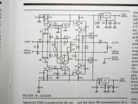
HPotter said:Maybe I made mistake, maybe not. It's not exactly the same circuit but pretty close. It appeared in 1990 issue of Audio Amateur.
From my observations the SE balanced line amp I posted in the beginning appeared 3 years ago and was probably influenced by Nelson Pass balanced SE preamps designs. But I might be wrong again.
The schematic came out of May 2002 issue of Audio Electronics
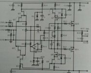
Ummm..... gentlemen. These are not the same design. Look closer... No BJTs in new one. A very worthwhile change. I guess that's why he called it The All-Fet Line Amp. The devil is in the details as they say. Maybe some of you will go read Mr. Borbelys Jfet articles someday......
Ummm..... gentlemen. These are not the same design. Look closer... No BJTs in new one. A very worthwhile change. I guess that's why he called it The All-Fet Line Amp. The devil is in the details as they say. Maybe some of you will go read Mr. Borbelys Jfet articles someday......
Attachments
Gents
I think this thread would get more done if the design of the magic preamp took a more logical direction.
Everyone has a pet gain stage, and they could be debated from now to the end of time. Why not spec the gain stage interface.
1. Board size
2. connection to the rest of the preamp.
3. power options
With some of these areas defined we could all make up amp boards and exchange them. This way after all of the contenders had done the tour a winner could be seclected. Every one could pick there own winner for that manner.
Just a thought.
we'll standardize later
... once we get some candidates for trial!
it is very difficult to design a standard for those things before we even know what all the permutations are. it would end up becoming a limiting factor. besides, most of our initial mockups will probably be messy hard-wired blobs (the parts are cheap for the most part so prototypes are expendable).
To me, these circuits are pretty different. Swapped FETs for bipolars, used different (newer) regulators to power the thing, different bias points, etc. The topology may be similar in principle - one could make a "BOZ" with bipolars, but no one mentions that and I don't think anyone has played with such a creature.
For DC performance, how about biasing the devices at the zero tempco point (after you find it!) and doing something with the physical design to keep things thermally under control (potting the circuit, choosing other circuit elements with complementary thermal drifts, etc.). They used to do stuff like that in the "old days" with instrumentation gear, instead of slapping a servo around it.
I've built Borbely's older circuit (the one with bipolars) a while back. It sounded very nice in my system as I recall. Maybe I'll have to dig it out and fire it up again (if I even still have it).
Harry, thanks for the 10V cascode tip; I've got some experiments to try...
mlloyd1
HPotter said:Maybe I made mistake, maybe not. It's not exactly the same circuit but pretty close. It appeared in 1990 issue of Audio Amateur.
For DC performance, how about biasing the devices at the zero tempco point (after you find it!) and doing something with the physical design to keep things thermally under control (potting the circuit, choosing other circuit elements with complementary thermal drifts, etc.). They used to do stuff like that in the "old days" with instrumentation gear, instead of slapping a servo around it.
I've built Borbely's older circuit (the one with bipolars) a while back. It sounded very nice in my system as I recall. Maybe I'll have to dig it out and fire it up again (if I even still have it).
Harry, thanks for the 10V cascode tip; I've got some experiments to try...
mlloyd1
Man, take an hour or two off to etch a circuit board and it takes umpteen pages to catch up.
Kudos to all for well-focussed posts. Thank you. Keeps me from getting ugly e-mail, which I appreciate. I'm singling out for special notice Harry and Jocko...I know it's killing you guys, but thanks anyway.
I'd like to suggest the following:
1) Build the newer Borbeley.
2) If time and resources are available, build the older one too, just for comparison.
3) Socket (no complaints about socketed components, please) the opamp, so as facilitate swapping parts in and out, as per Jam's post on servo sound being related to choice of opamp.
4) No, sorry, I can't volunteer to build anything at the moment for two reasons--One, I'm up to my behumpus in last minute details on Aleph-X and X line stage and, Two, lack of rescources, both parts and money with which to buy them.
5) If the circuit starts making the rounds I wouldn't mind a chance to listen to it, though. Frankly, I'm pulling for the JFET version, but perhaps I'm just prejudiced.
Grey
If time and resources are available, build the older one too, just for comparison.
You're joking right? Erno Borbely has been tweeking this topology for over a decade. Why go down that road again, nostalgia? Please no more diversions.... Psssttt..... I'll let everyone one in on a secret that that just about every professional audio designer with ears knows, FETs sound better than BJTs and they are not any harder to design with for preamp and amplifier circuits.
H.H.
mmmhhh the Zero Tempco point... Make an current source which feed the source (Sound good!? hehehe) of the JFet's then this should be History then you can concentrate on Vgs matching. .. I will possible get a hit in the face for this one, but it is what i see from my point of view.
Harry you never know if there is some new BJT's around performing better 😀 ... Just fun..... Teasing!!!!
Regarding board design ... Give me a schematic and i will make a PCB design fast... Last time my father was etching board i got 0.5 hour to make a PCB for my preamp... i did it with no failures and a big nice groundplane!!!!
Beat this!
Sonny
sonnya said:
Regarding board design ... Give me a schematic and i will make a PCB design fast... Last time my father was etching board i got 0.5 hour to make a PCB for my preamp... i did it with no failures and a big nice groundplane!!!!
how do you make your PCBs??? i've tried toner transfer with mixed results, it is a pain. do you use standard positive photo-resist? i guess you have a pretty nice setup...
Re: If time and resources are available, build the older one too, just for comparison.
hmmmmmm... i know some people who will take issue with that but i'll let it lie just to keep us on-track. 😛
HarryHaller said:Psssttt..... I'll let everyone one in on a secret that that just about every professional audio designer with ears knows, FETs sound better than BJTs and they are not any harder to design with for preamp and amplifier circuits.
H.H.
hmmmmmm... i know some people who will take issue with that but i'll let it lie just to keep us on-track. 😛
Well I didnt quite expect that my posting would inspire such a response but i'll try to respond to the questions that have arisen....
JFet was for the diff amp input pair.
BJT or MOSFET for the cascode i'll leave it to the individual... i prefer MOSFET here.
I'd probably use BJT current sources (but i could be convinced to try others in this instance) where required and passive resistor bias elsewhere.
Folded cascode provides a more pure signal path and is a single stage.
Higher voltage allows more voltage swing, easier passive bias for the output and generally better specs in most instances such as stray capacitance and so on.
Please no servos.
Folded cascode provides a more pure signal path and is a single stage.
?????????????!!!!!!!!!!!!!! I think you are going to have to back that one up with some explaination. I, for one, have absolutely no clue as to what you are talking about. I am all ears........ High rail voltages are a trade off as to device dissapation (voltage x current) One would like to run the mosfets at as high a bias current as possible for hghest transconductance and linearity. Also, higher voltage caps and transformer cost more money. I can't really see much need for more than +/- 25 volt rails for a line level circuit.
H.H.
- Status
- Not open for further replies.
- Home
- Amplifiers
- Solid State
- The diyAudio.com preamp project!