Hi djk,
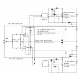
That is simplified to the point where many may not realise that the "tracking" elements can be more than one technology. As shown you (in a general form) have some mosfets driven by an offset in a linear manner. These could just as easily be a PWM supply, the signal take off point may be earlier in the amplifier. Even the input.
What I am trying to point out is that the idea is more important that the way it is represented. There is more than one way to skin a cat.
BTW, djk, I agree with you. There is no way I can see you wasting the time in capture (takes forever). Pointing to similar work is just as good to illustrate an idea.
-Chris
As far as I understand, the diode is used because it is cheap and simple and because if everybody uses it “me too”.
We are so used to see the dam diode there that we don’t think on other solutions; it’s a king of sch folklore.
Maybe we could replace it by a controlled switch; one that provides trapezoidal voltage instead of square.
We are so used to see the dam diode there that we don’t think on other solutions; it’s a king of sch folklore.
Maybe we could replace it by a controlled switch; one that provides trapezoidal voltage instead of square.
Hi TOINO,
A diode is the correct device to use in this case.
Just imagine what would happen if you reverse bias any current active linear device. If you guessed component failure, followed by smoke, you'd be right.
A diode is a cool little device. It works on autopilot without having to be controlled. The on-off characteristics can be adjusted by device type and passive components. The fact that they are used all by themselves indicates that there are no big problems to solve with them. It's normal operation includes both forward and reverse bias.
And they are cheap. 😀 😀 😀
-Chris
The newer Schottky are much better than any of the high-speed diodes previously used.
Why were they not used before?
25+ years ago no low-cost high-voltage Schottky diodes existed.
Why were they not used before?
25+ years ago no low-cost high-voltage Schottky diodes existed.
Hi djk,
Still, those products had other evils lurking about. Why change just one?
-Chris
There were no meaningful complaints about the sound quality. Nothing to affect product sales, so no reason to install a better part.The newer Schottky are much better than any of the high-speed diodes previously used.
Still, those products had other evils lurking about. Why change just one?
-Chris
Hi Folks,
I have just figured out that in Class-G amp[both in simulation and real world lab tests], if the Upper and Lower Tier devices are connected in parallel rather than series , then the Glitches are much less than with series combination.....
Is there any patent with parallel connection of class-G amp...
for reference MX1500 from QSC uses parallel connected output devices rather in series....
http://www.qscaudio.com/support/library/schems/mx1500.pdf
Cheers,
K a n w a r
QSC has a patent on the current limiting circuit on that amp, but not the output stage (I think).
Yamaha did a parallel output stage with progressivce drive about 20 years ago.
Yamaha did a parallel output stage with progressivce drive about 20 years ago.
djk said:QSC has a patent on the current limiting circuit on that amp, but not the output stage (I think).
Yamaha did a parallel output stage with progressivce drive about 20 years ago.
Hi DJK,
After some searching i found that QSC has a patent on "Time Based Output Short-Circuit Averaging protection"
Whats your view regarding parallel stage...
K a n w a r
There were no meaningful complaints about the sound quality. Nothing to affect product sales, so no reason to install a better part.
😀 😀 😀 😉
Revisited
Thats why I used only Schottkys in case of Commutation Diodes.
regards,
K a n w a r
djk said:The newer Schottky are much better than any of the high-speed diodes previously used.
Thats why I used only Schottkys in case of Commutation Diodes.
regards,
K a n w a r
"Whats your view regarding parallel stage..."
The older MX2000 sounds better than the MX2000A, for what it's worth.
The Crest CA9 sounds better than those, it's class G (they call it class H, but it's linear, not a hard switch). I'm sure the OPA2604 vs the NE5532 makes a small difference, but the current limiting circuit QSC uses really makes them sound less than perfect. The dynamics are really poor. QSC uses a pair of adjustable load resistors on they output of the 5532, and depend on the current limit in the IC.
The Leach LSR&D 101 will kick either amp to the curb (with only ±63V rails, two 20,000µF caps, a 1KVA transformer, and three pair of MJ15011/12 per channel ). Driven slightly into clipping it still sounds cleaner than the QSC, and has a lot more slam in the bass. Funny how that works out, a 160W/8R hi-fi amp vs a 1KW/2R PA amp (the speakers used were a 2R load).
Hi Anatech & DJK,
I just made the switching threshold detector much simpler just by eliminating the comparators and driving the LED's from the VAS directly for Tier Transistion.......much simpler and low cost as well.
regards,
K a n w a r
I just made the switching threshold detector much simpler just by eliminating the comparators and driving the LED's from the VAS directly for Tier Transistion.......much simpler and low cost as well.
regards,
K a n w a r
Hi Folks,
Just 5 Pairs of IRFP360 were enough to Pump out 2.2KW in 4 Ohms with rails sagging 10 Volts below idle state.....
Cheers,
K a n w a r
Just 5 Pairs of IRFP360 were enough to Pump out 2.2KW in 4 Ohms with rails sagging 10 Volts below idle state.....
Cheers,
K a n w a r
News Updates
Hi Folks,
PCB Designing is undergoing for a 2 Tier Class-H Bipolar version[Lower Power] and All Vertical N-channel Mosfets version[Higher power]:
BP Version:
Dual Differential Cascoded Frontend+ Classic CE VAS but might be with EF buffer all trannies A42/92 @1mA VAS MJE340/350 @ 5mA
Triple EF output Stage ->MJE350/340->C5200/A1943 & using 5 Pairs of C5200/A1943 at output targetted for 1200W @ 2 ohms only
---------------------------------------------------------------------------------
NVMOS version
Dual Cascoded Dfferential Front end + Rush-Cascode VAS + P-P Mosfet drivers + 2 pairs of APT20M18LVR at the output fo 2.5KW @ 2 ohms .. All Trannies A42/92....
---------------------------------------------------------------------------------
IRFP260N/APT20M18LVR as Rail Switchers+TLP250 opto Gate Drivers...
STPS150C20 Schottky's for commutation diodes....
NE5532 dual opamp configured as complementary comparator for switching threshold detectors.
after completion ,I will post some pics
Thanks to all!
K a n w a r
hi kanwar,
could you kindly post updated schematics
your thread is very interesting...
thanks,
roland
could you kindly post updated schematics
your thread is very interesting...
thanks,
roland
- Home
- Amplifiers
- Solid State
- The Class - H Amplifier