My "Almost Blameless" amp is now packaged, and the bias is tweaked up. I'll take some pics and try to make it sing for me tomorrow.... Schematics to follow, too. The look is stark/functional/proletarian.

janneman said:My experimental error correction / zero global nfb amp is playing. Beautiful, of course. 😉
Almost ready to travel. Only the protection to tweak.
Jan Didden
Looking good Jan

Magura 🙂
Hi Jan,
That looks really cool.
Is that 'PaX' text engraved on the panel or just done with an image editor ? Something 'different' about it .
Could be the lighting ?
Cheers.
That looks really cool.
Is that 'PaX' text engraved on the panel or just done with an image editor ? Something 'different' about it .
Could be the lighting ?
Cheers.
Looks funny isn't it? Actually, the letters are laser cut, and I put some copper foil behind it. But the lighting changes it to look like it actuallly is positive relief.
Jan Didden
Jan Didden
I love it!
Hey Jan,
That looks absolutely amazing!! 😎
Very, very nice. Clean, yet beautiful.
-Chris
Hey Jan,
That looks absolutely amazing!! 😎
Very, very nice. Clean, yet beautiful.
-Chris
Hi SY,
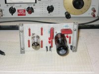
Is that the "Perf Board Palace"? 😀 MK1 of course.
Could that be a 334A in the background? Certainly looks like it. I think the 333A was identical except no AM detector (not normally required for audio work).
-Chris
Is that the "Perf Board Palace"? 😀 MK1 of course.
Could that be a 334A in the background? Certainly looks like it. I think the 333A was identical except no AM detector (not normally required for audio work).
-Chris
Re: The ImPasse preamp
SY, how did you make an anti-slip mat into a circuit board?
😀 Please describe design. Very nice. What's with the name?
SY said:Bench tested and ready to be mounted in the case.
SY, how did you make an anti-slip mat into a circuit board?
😀 Please describe design. Very nice. What's with the name?
333A. Some Canadian guy insisted that I buy it.😉
Perf board doesn't get enough respect. It really is (as regards strays and leakage) closer to point-to-point than it is to PCB. The other modules (raw PS, regulators, output cap board) are also on perf. It's lousy for production but perfect for one-off.
Perf board doesn't get enough respect. It really is (as regards strays and leakage) closer to point-to-point than it is to PCB. The other modules (raw PS, regulators, output cap board) are also on perf. It's lousy for production but perfect for one-off.
janneman said:My experimental error correction / zero global nfb amp is playing. Beautiful, of course. 😉
Almost ready to travel. Only the protection to tweak.
Jan Didden
Of course, what we REALLY want to see is what's inside...
/Hugo
What's with the name?
It's designed specifically to drive the F4. So I couldn't resist the pun. (Zen Mod would have been happier if I called it "Smashing Pumpkins")
As you can see, it's a very simple design. No loop feedback. Gain of 20. Surprisingly low distortion at the 20V output needed. It will only drive balanced loads, but it's not supposed to be universal. Input tube is a CV1988 (British military version of 6SN7) from Morgan Jones's stash. Output tube is a "Bugle Boy" ECC88.
And surprise, surprise, active regulation, CCS loads, and LEDs. My design work does tend to follow a pattern.
Unlike Jan's amp, it will NOT be beautiful.
SY said:Unlike Jan's amp, it will NOT be beautiful.
But, as they say in my country, it'll play the stars down from heaven 😉
Jan Didden
So, as you may have read elsewhere, I got the title of "award manufacturer" for this years event.
Now you can see what the awards turned out to be 🙂
I realize the pics are not the best, but it's dark here and I had no light handy, and couldn't move the knobs as the glue isn't hardened yet.
The materials are walnut and copper.....
http://www.briangt.com/gallery/album64
So, if you want a set, drop by the event and show us something you've made 😀
Magura 🙂
mpmarino said:...funny looking cookies ..😕
Yeah, and you won't get them! 😎
Magura 😉
Attached is a picture of the "Almost Blameless" amp I'm bringing. This started as a training exercise in analog simulation I gave to a new guy at work. I gave him a back-of the envelope schematic for a basic amp so he could do some Orcad simulations and get a feel for a simple design and see what some changes would do to the operating parameters.
It started out as a simple JFET differential input stage, VAS, and darlington outputs w/VBE multiplier. I got hooked by the design myself, , added some buttons and bows, then decided to build it with what I had at hand, since the simulation results were very attractive. The design originally called for +/-30V rails, but the only transformer I had on had gave me a +/- 40V supply, and the darlingtons available (TIP142/147) had a pathetic SOA at 80V, so the output was changed to MOSFETs, and the VBE multiplier to a VGS multiplier. The amp was packed into an LMB box, and the result is shown below - plain but functional.
It started out as a simple JFET differential input stage, VAS, and darlington outputs w/VBE multiplier. I got hooked by the design myself, , added some buttons and bows, then decided to build it with what I had at hand, since the simulation results were very attractive. The design originally called for +/-30V rails, but the only transformer I had on had gave me a +/- 40V supply, and the darlingtons available (TIP142/147) had a pathetic SOA at 80V, so the output was changed to MOSFETs, and the VBE multiplier to a VGS multiplier. The amp was packed into an LMB box, and the result is shown below - plain but functional.
Attachments
mpmarino said:...funny looking cookies ..😕
no,silly, those are buttons ........ brown ones .

- Status
- Not open for further replies.
- Home
- General Interest
- Everything Else
- The Burning Amp Festival-Burning Gadgets Preview