The MOSFET gates are only protected in one direction, because of the 1N4148s in series with the Zeners. Is there any way the PMOS could have been blown up by a too positive gate voltage?
When the Zeners conduct, what is supposed to limit the current through them?
When the Zeners conduct, what is supposed to limit the current through them?
Last edited:
Maybe. But at full clipping, they don't see more than +-5V. If something else breaks, all bets are off, of course.The MOSFET gates are only protected in one direction, because of the 1N4148s in series with the Zeners. Is there any way the PMOS could have been blown up by a too positive gate voltage?
The gate stoppers.When the Zeners conduct, what is supposed to limit the current through them?
The gate stoppers will also act as crude fuses. If something fails catastrophically so the VGS goes bonkers, the gate stoppers will quickly go open circuit. I’m deliberately keeping them 1/4W for that reason. They should pop before the zeners do.

It works again! I found two poor solder joints: One on a protection diode and one in a current generator. The latter could have made it put out DC. It might have failed when the PCB got warm and started to expand. It actually took out both MOSFETs. My guess is that it took out the top one first, created a short and blew the bottom one.
I also increased R6 to 33ohms to keep Q12 comfortable even during a saturation event. I will, once I figure out where I misplaced my 5.6V zeners, take @stigigemla 's advice and replace D4 and D6 with zeners. I might whack in some base stoppers on the next rev of the PCB.
As usual, thanks for all your pointers and expertise!
This is not necessarily. Zener diode series with switching diode is pretty much industrial standard. Hafler Lateral MOSFET amps all use this practice without issues.I will, once I figure out where I misplaced my 5.6V zeners, take @stigigemla 's advice and replace D4 and D6 with zeners.
Switching diodes have less junction capacitance comparing to Zener. Thus, it has less load on the gate signal.
All the embarrassing messing up aside, I do like this step response! I sounds really crips on things like cymbals and snare drums, and I think I have the slew rate to thank for that. This is into a 8ohm resistive load.

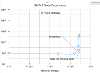
As said, the protection diodes should be installed in front of the driver transistors, right after the VAS to maximize the protection capability. Otherwise, the driver transistors could brute force them as they don’t exist.Compare the capacitance of the zener with the 1660pF input capacitance of the transistor.
Here is the capacitance of another zener diode. It could be more or less for the one used in this circuit.
Aaahh... Clipping without smoke. Love it!

re-check clipping at 10KHz
input filter is 10MHz ! - that serves no purpose - re-check slew with a proper filter
input filter is 10MHz ! - that serves no purpose - re-check slew with a proper filter
The output impedance of the signal source is unknown. It could be a volume pot. That position is not good for input filtering. However, the RC network is still beneficial. It keeps the input capacitive. A capacitive input has less chance to oscillate than an inductive source.input filter is 10MHz ! - that serves no purpose - re-check slew with a proper filter
You're absolutely correct and this is something I should have addressed. The way my amp is set up right now causes the frequency response to vary with volume. It's well above audible range, but it's bad practice nonetheless.The output impedance of the signal source is unknown. It could be a volume pot. That position is not good for input filtering.
I redesigned it and placed the pot after the filter. This is what I get with a 50k pot for 25%, 50%, 75% and 100%. The PCB will have connectors for the pot and if you don't need it, you just short it out.
I've installed it and hooked it up to speakers, so I can't test it right now. But it clips perfectly fine at 10kHz in the simulation, which has proven to be almost scary similar to the physical build, so I have no reason to believe it would have a problem at 10kHz. I'll test it next time I'm messing with the amp!re-check clipping at 10KHz
I changed that cap to 220pF when I built it but forgot to update the schematic, so it's 5MHz. I also redesigned the whole input section as shown above.input filter is 10MHz ! - that serves no purpose - re-check slew with a proper filter
Q2's base current flows into the wiper of the potmeter, so when the contact resistance varies when you change the volume setting, it won't just modulate the signal but also cause cracking noises during silence. It's better than direct current out of the wiper, which can cause anodization of the wiper of a carbon potmeter according to an application note I read long ago, but still, I'd reserve space for an AC coupling capacitor between the wiper and R2.
- Home
- Amplifiers
- Solid State
- "The Bog Standard" - A good enough amplifier for the rest of us