Hi to u all,
has anyone heard about the class B Blomley amplifier.It appears that it can sound as good as a class A amplifier according to Audio Express magazine.Those who have built that amplifier,can they share with us their experience and detail how the amp works.
Thanks.
has anyone heard about the class B Blomley amplifier.It appears that it can sound as good as a class A amplifier according to Audio Express magazine.Those who have built that amplifier,can they share with us their experience and detail how the amp works.
Thanks.
Are you referring to a design by Peter Blomley appearing in Wireless World magazines for February and March 1971? I built a pair of this design and had them in use for several years.
The main attribute of this class B design is that neither output device goes into cutoff, rather they stop short by around 20mA. Forum member Valery Vzaischenko is offering a design called NS (Non Switching) that does the same thing.
The Blomley design uses a "signal splitter" stage to prevent cutoff in the output stage half that that would otherwise be biased off with appropriate signal polarity. The object is to reduce crossover distortion by eliminating charge storage in turned off transistors.
Keith

Blomley Amplifier
To Keith,
yes the Blomley amp was described in the magazines you mentioned but i have not checked on American Radio History if they have the mag and in what state is the publication.its so old.Audio Express said that it is an old technique brought to life again.if those who built it say that the sound is impressive,i might try to build it if i can get the schematics.My actual amplifier is the John Linsley Hood class A which i built almost 18 years ago and is satisfactory for my small listening room.
Hello revenant. Check out the Thread Class aP amplification" in the Pass Labs Forum. The notation aP means analog pulse. This approach expands on and is maybe more versatile than Blomley's; amp because of its broad scope of use.
There was a recent article on the Blomley over on 'allaboutcircuits'. Its a great read.
My 40-Year Love Affair with a Remarkable Amplifier—A Class B Amplifier for Audiophiles
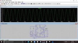
I also did a sim for curiosity. You will need to put your own models into it and alter voltage source V1 to get the desired quiescent current:
My 40-Year Love Affair with a Remarkable Amplifier—A Class B Amplifier for Audiophiles
I also did a sim for curiosity. You will need to put your own models into it and alter voltage source V1 to get the desired quiescent current:
Attachments
Blomley Amplifier
Hi to u all,
Thank you for advice and schematics.I imagine the semiconductors in use in 1971 are no more available now.I have not yet gone in detail through the article but i will revert to u in case i need further advice,thanks.
Hi to u all,
Thank you for advice and schematics.I imagine the semiconductors in use in 1971 are no more available now.I have not yet gone in detail through the article but i will revert to u in case i need further advice,thanks.
The amp should work just fine with modern semiconductors although the germanium diode might be harder to source these days. I wouldn't foresee a problem though, even in replacing the diode with something a little different such as a transistor type vbe multiplier and suitable resistor to modify its characteristic. That's all just fine tuning the design though.
Thank you Mooly and all for the relevant references which are informative and inspirational.
Any idea Keith Taylor how the non switching amp by V. Vzaischenko differs from that of Blomley's? A thread maybe. Thanks.
Best
Anton
Any idea Keith Taylor how the non switching amp by V. Vzaischenko differs from that of Blomley's? A thread maybe. Thanks.
Best
Anton
Hi Mooly, All,There was a recent article on the Blomley over on 'allaboutcircuits'. Its a great read.
My 40-Year Love Affair with a Remarkable Amplifier—A Class B Amplifier for Audiophiles
I also did a sim for curiosity. You will need to put your own models into it and alter voltage source V1 to get the desired quiescent current:
BTW that article by Dermot Herron includes a link to the EW/WW articles
http://www.keith-snook.info/wireless-world-magazine/Wireless-World-1971/New%20Approach%20to%20class-B%20Amplifier%20Design%20by%20P%20Blomley.pdf
He mentions there was a patent that prevented him commercializing it. A lot of good amp designs are dismissed wrongly just because they are never commercialized.
Douglas Self tried it but couldn't see any benefit (read here). That doesn't mean it is no good either.
Thanks for you sim circuit. BTW the amp should drive 15 ohms.
I found the distortion falls when the splitter bias is voltage is 1.05 volts.
I added a distortion weighting circuit (attached) so you can see the weighted crossover wobbles by plotting Vout and D2. As a guide if the weighted plot (D2) has distortion that you can see (with full screen but not zoomed) then you can hear it. D2 means the second derivative (slope of the gain) which is roughly the roll-up slope of our hearing from bass (50-100Hz) up to midrange frequencies (1-3kHz). It is best to use 50Hz or 100Hz when weighting since more crossover harmonics fall in the sensitive hearing range making the readings more meaningful to what we hear.
The ErrorLog shows the weighted THD. It is about 100 times the unweighted THD. Typical Lin Topology weighted THD's are around 30 times and Class-A typically about 3 times. The Blomley is higher factor because the splitter stage transitions through crossover faster due to current drive of the splitters (Tr4,5). Current drive can give lower unweighted THD's than the Lin Topology using voltage driven output stage but with a faster transition the higher harmonics are more audible. So is much really gained in terms of reducing audible crossover distortion?
Have a play with changing the bias voltage and watch the unweighted THD and weighted THD (also monitor the power transistor's currents at crossover). Notice the unweighted THD doesn't change much (due to dominant low order harmonics) but the weighted THD changes hugely. This shows how useless ordinary THD readings are as an indicator of what we actually hear. Do an FFT plot of Vout and D2 -- notice with D2 the high harmonics dominate.
There is merit in the way Peter Blomley keeps the power transistors slightly on over the full cycle so 1) they are just outside their nonlinear exponential region, and 2) the input voltage changes are smaller improving the output stage bandwidth and allowing a bit more global feedback, 3) the bias point is outside the power transistor heating zone so there should be very little thermal lag distortion.
Keeping modern RET power transistors slightly on is important to keep their FT high. The Blomley approach is therefore very relevant today's transistors. Erik Margan achieved a similar thing, a thread here, article here. He did show there is a useful sonic improvement by keeping the power transistors always slightly on -- a pity he never weighted the harmonics for a better numerical comparison. BTW I notice his power transistors don't have base-emitter resistors (EW Fig 2) so does it suffer from cross-conduction?
If I can put in a plug for my Cube-AB amps, they overcome the problem of high order crossover distortion by following a cube curve and glide smoothly through crossover; this generates mainly 3rd harmonic distortion which can easily be made inaudible with only 20dB of feedback (that's less than is used in most output stage before global feedback). See page 17 here for more details. Weighting harmonics is a key to understanding what makes an amplifier sound good or not so good.
Attachments
Last edited:
Thank you Ian,
This is very interesting although I don't fully understand all your points. I considered the Blomley a few years ago but felt setting the correct bias more trouble than it seemed because of varying temperature operation. Later, with an EE friend here in Melbourne we examined Alison output stages, and again, found that benefits were not strictly worthwhile for the additional complexity and additional actives. Notwithstanding I'd be delighted to be proved wrong.....
I read all your posts with great interest. Thank you for contributing to DIYaudio with meaty, substantial information.
Hugh
Any idea Keith Taylor how the non switching amp by V. Vzaischenko differs from that of Blomley's? A thread maybe. Thanks.
Revisiting some "old" ideas from 1970's - IPS, OPS
As far as I can tell the NS OPS (Non Switching Out-Put Stage) is first introduced at post 144. Post 328 has more info including waveforms in the crossover region.
Keith
A modern interpretation of the Blomley basics...
...
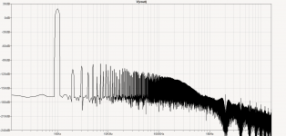
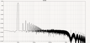
has led me to wonder if the results shown below exhibit a worthwhile order of improvement?
It's still very much a work in progress but an informed or even critical answer to this question would be very welcome...
The circuit is now DC coupled throughout, has split 30V rails with a new front end and a servo to boot. It clips nicely without threatening damage and seems comfortably 4 Ohm capable.
Both FFT's shown are into an 8 Ohm load and in each case the static output current is ~100ma. For the NS variant the 'off side' minima is about a third of this and for the standard non NS one it naturally goes to zero.
As may be seen in the FFT's and attached TIAN probe results, the amp's performance is reasonably representative of typical 'real world' designs. It has an acceptable ULGF and sensible margins. It has been compensated using a topologically specific application of otherwise tried and tested techniques using only R&C components.
Smilarly to Hugh's earlier indication; not all of what Ian has posted above is yet sufficiently clear to me.
In the context of this example, I hope that Ian's or someone elses's answer will help to make the subject of harmonic weighting more readily understood.
With thanks in advance
Cheers, ian
...
...
has led me to wonder if the results shown below exhibit a worthwhile order of improvement?
It's still very much a work in progress but an informed or even critical answer to this question would be very welcome...
The circuit is now DC coupled throughout, has split 30V rails with a new front end and a servo to boot. It clips nicely without threatening damage and seems comfortably 4 Ohm capable.
Both FFT's shown are into an 8 Ohm load and in each case the static output current is ~100ma. For the NS variant the 'off side' minima is about a third of this and for the standard non NS one it naturally goes to zero.
As may be seen in the FFT's and attached TIAN probe results, the amp's performance is reasonably representative of typical 'real world' designs. It has an acceptable ULGF and sensible margins. It has been compensated using a topologically specific application of otherwise tried and tested techniques using only R&C components.
Smilarly to Hugh's earlier indication; not all of what Ian has posted above is yet sufficiently clear to me.
In the context of this example, I hope that Ian's or someone elses's answer will help to make the subject of harmonic weighting more readily understood.
With thanks in advance
Cheers, ian
...
Attachments

Last edited:
For the sake of completion...
...
the same applies as above but this time at 100Hz.
For both frequencies the NS harmonic roll off rate looks to be around 65 or so dB per decade.
Is there some analytical approach or method of inspection which can be used on closed loop results to derive a simple first order figure of merit?
Thanks ian
...
...
the same applies as above but this time at 100Hz.
For both frequencies the NS harmonic roll off rate looks to be around 65 or so dB per decade.
Is there some analytical approach or method of inspection which can be used on closed loop results to derive a simple first order figure of merit?
Thanks ian
...
Attachments

Hello All,
Thank you Ian for your earlier post. I have Vol. 8 of Linear Audio which has your article. A lot of great food for thought therein both.
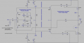
The Blomley amp may be mysterious to some because of its unusual operation. I hope the attached schematic can provide added clarity as follows. The .asc file runs without problems and is fun-informative to fine-tune.
1. The amp is in two parts. They are separated by the $-sign vertical boundary.
2. To the left of the boundary is an Op Amp-based complementary symmetry precision rectifier [CSPR]. It cuts the music signal at its zero crossing to give positive and negative going pulses. This is required by the Blomley approach.
3. TP1 and TP2 at the output of [CSPR] show the rectified negative and positive going pulses respectively post running the .asc file. This is the location where the mystery operation of the regular Bromley amp disappears.
4. The pulses in point 3 are presented to the complementary symmetry power output stage. The complementary-symmetry [CS] bjt buffer drives the gates of the [CS] Mosfets and also adjusts their idle bias.
5. One can separate the operation of each power Mosfet; done before applying overall negative loop feedback so as to get the optimal symmetry of the operational waveforms. Ground the Mosfets' joined drains. View the resulting pulse-currents flowing through the 0.1 Ohm sense resistors at TP3 and TP4. I couldn't make'm equal in amplitude; most probably because of an intrinsic difference in their trans-conductance. Note; their idle bias does not go to zero per the requirement of the Blomley approach.
6. Overall negative feedback to the inverting input of the Op Amp cleans up performance. The power output stage needs more voltage gain [like that in Blomley's] for an even lower distortion.
I've had and continue to enjoy a 22 years + love affair with the Blomley methodology.
Best
Anton
Thank you Ian for your earlier post. I have Vol. 8 of Linear Audio which has your article. A lot of great food for thought therein both.
The Blomley amp may be mysterious to some because of its unusual operation. I hope the attached schematic can provide added clarity as follows. The .asc file runs without problems and is fun-informative to fine-tune.
1. The amp is in two parts. They are separated by the $-sign vertical boundary.
2. To the left of the boundary is an Op Amp-based complementary symmetry precision rectifier [CSPR]. It cuts the music signal at its zero crossing to give positive and negative going pulses. This is required by the Blomley approach.
3. TP1 and TP2 at the output of [CSPR] show the rectified negative and positive going pulses respectively post running the .asc file. This is the location where the mystery operation of the regular Bromley amp disappears.
4. The pulses in point 3 are presented to the complementary symmetry power output stage. The complementary-symmetry [CS] bjt buffer drives the gates of the [CS] Mosfets and also adjusts their idle bias.
5. One can separate the operation of each power Mosfet; done before applying overall negative loop feedback so as to get the optimal symmetry of the operational waveforms. Ground the Mosfets' joined drains. View the resulting pulse-currents flowing through the 0.1 Ohm sense resistors at TP3 and TP4. I couldn't make'm equal in amplitude; most probably because of an intrinsic difference in their trans-conductance. Note; their idle bias does not go to zero per the requirement of the Blomley approach.
6. Overall negative feedback to the inverting input of the Op Amp cleans up performance. The power output stage needs more voltage gain [like that in Blomley's] for an even lower distortion.
I've had and continue to enjoy a 22 years + love affair with the Blomley methodology.
Best
Anton
Attachments
Logician,
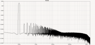
The FFTs reveal a profile very similar to a well compensated, modern 'competent' design. That is, it has H3 higher than H2, H5 higher than H4, and H7 higher than H6. There is a long series of harmonics to the 200th created by the heavy global feedback.
I have not built this particular circuit but I have discovered that there is a relationship to harmonic profile and sound quality, almost regardless of THD. I would expect this amp to sound 'hifi' but not musical, unlike many of Pass' DIY amps, particularly the Zen series, and the JLH 10W which despite high THD sound wonderful. I agree that the high pole at 3MHz and very good phase margin is outstanding, but these do not make good sound quality.
People disagree about THD and sound quality. I would expect the Blomley with its non-switching output stages to deliver very low high, odd orders; but from Ian's FFTs these objectionable harmonics do appear, much like most AB modern amps.
Perhaps global feedback is part of this? But why does the non-switching advantage reveal very low levels of high, odd orders?
HD
Keeping modern RET power transistors slightly on is important to keep their FT high. The Blomley approach is therefore very relevant today's transistors. Erik Margan achieved a similar thing, a thread here, article here. He did show there is a useful sonic improvement by keeping the power transistors always slightly on -- a pity he never weighted the harmonics for a better numerical comparison. BTW I notice his power transistors don't have base-emitter resistors (EW Fig 2) so does it suffer from cross-conduction?
As a side note, if anyone would want to sell non-switching class B amplifiers, please choose a different abbreviation than Erik Margan did. In my country NSB has a rather different meaning.
National Socialist Movement in the Netherlands - Wikipedia
Harmonic roll-off rates for assessing crossover distortion
After writing my Vol.4 article I realised that the rate of roll-off of harmonics in -xdB/decade is an easier way when doing simulations to assess whether high order harmonics like from crossover distortion than adding a special weighting filter. You can do it by placing a ruler on the FFT plot and slide the ruler to say 0dB and start of a decade and read off the dB drop at the next decade. Easy as.
If you read anything less than -50dB/decade then crossover distortion will most likely be the dominant distortion in the sound of the amp -- then you need to check if the weighted THD is below about 1%, eg by using the double differentiator I used in Post 10 and RMS add all harmonics to the 100th with a 100Hz fundamental; the ErrorLog THD using ".four {freq} 100 V(D2) ". You probably want a 20dB safetey margin, that's a target of ~0.1% for D2 100 harmonics with 100Hz to be safe enough to say any HD will be inaudible at this power level. Note a double differentiator is +40dB/decade not the +50dB/decade of our hearing so it under estimates what we can hear, but this is partly offset by taking harmonics to 10kHz (rather than 3kHz where our hearing sensitivity to falls).
Effectively the double differentiator magnifies all the higher harmonics so they can appear on a FFT plot of V(D2) at the same relative audibility as the lower order harmonics. And when D2 is displayed on an o'scope IF you can see any harmonic distortion then it's most likely you can hear it as well from your amp.
---
The two plots you gave with 100Hz, the first with NS and about -60dB/decade harmonic roll-off is very good. Also the first low order harmonics are -120dB below fundamental, so low that they would be hard to measure let alone hear.
The second without NS has about -30dB/decade, but with the first low order harmonics at -120dB below fundamental you have a safety margin of +80dB (below 1% needed for audibility). So even if you weighted the higher harmonics they are unlikely to get to -40dB to become audible (at least at the output level used here).
You can conclude that 1) NS does in fact reduce high order distortion, and 2) that the distortion even without the NS is not likely to be audible.
---
Regarding the Blomley approach, which uses 1) current drive of the splitters, and 2) non-switching in the power stage. The use of current drive of the splitters increases the amount of high order distortion compared to ordinary voltage drive splitting. Current drive of the splitters causes a faster transition through the zero-cross and a doubling of the rate when weighted with say +40dB/decade (double differentiator) gives 4 times the level of higher harmonics, that's a net increase of +20dB/decade. So unless current drive of the splitters can reduce the level of higher harmonics by -20dB/decade at the same time then you are not getting ahead by using current drive of the splitters.
An exception might be in the extreme case where the switching rate at the zero crossing is so fast that the majority of the higher harmonics are pushed above 20kHz where they don't affect the audible range (assuming there's not much other nonlinearites to created demodulation into the audio band by intermodulation). Antoinel's Class-aP (Post 5) would seem to fit into this category if the switching rate is fast enough. I'd be interested to see FFT plots and some D2 values for any of Antoinel's Class-aP amps.
Cheers
Unfortunately, my Linear Audio article in Vol.4 on harmonic weighting is behind a paywall, but I briefly cover it's application in my free Supplement on p17, mentioned in Post 10. The key point:...
the same applies as above but this time at 100Hz.
For both frequencies the NS harmonic roll off rate looks to be around 65 or so dB per decade.
Is there some analytical approach or method of inspection which can be used on closed loop results to derive a simple first order figure of merit?
Thanks ian
...
Why is the harmonic roll-off rate an important parameter? Our hearing sensitivity curves roll-up at
approximately +40 to+50dB/dec in the 1kHz to 3kHz range when multiple tones do not cause
masking. This means we want any harmonics from crossover distortion to roll-off faster than
-50dB/decade so harmonic distortion from crossover distortion cannot be heard.
Standard Class-B amplifiers have difficulty reducing the level of the higher order harmonics from crossover distortion due to:
1) Our ear boosts the higher order harmonics at about the same rate as they reduce so all are nearly equally apparent, and
2) The negative feedback factor of most Class-B power amplifiers rolls-off at 20dB/decade in the same frequency range where our ear boosts the higher order harmonics and this makes it hard to suppress crossover distortion and make it inaudible...
After writing my Vol.4 article I realised that the rate of roll-off of harmonics in -xdB/decade is an easier way when doing simulations to assess whether high order harmonics like from crossover distortion than adding a special weighting filter. You can do it by placing a ruler on the FFT plot and slide the ruler to say 0dB and start of a decade and read off the dB drop at the next decade. Easy as.
If you read anything less than -50dB/decade then crossover distortion will most likely be the dominant distortion in the sound of the amp -- then you need to check if the weighted THD is below about 1%, eg by using the double differentiator I used in Post 10 and RMS add all harmonics to the 100th with a 100Hz fundamental; the ErrorLog THD using ".four {freq} 100 V(D2) ". You probably want a 20dB safetey margin, that's a target of ~0.1% for D2 100 harmonics with 100Hz to be safe enough to say any HD will be inaudible at this power level. Note a double differentiator is +40dB/decade not the +50dB/decade of our hearing so it under estimates what we can hear, but this is partly offset by taking harmonics to 10kHz (rather than 3kHz where our hearing sensitivity to falls).
Effectively the double differentiator magnifies all the higher harmonics so they can appear on a FFT plot of V(D2) at the same relative audibility as the lower order harmonics. And when D2 is displayed on an o'scope IF you can see any harmonic distortion then it's most likely you can hear it as well from your amp.
---
The two plots you gave with 100Hz, the first with NS and about -60dB/decade harmonic roll-off is very good. Also the first low order harmonics are -120dB below fundamental, so low that they would be hard to measure let alone hear.
The second without NS has about -30dB/decade, but with the first low order harmonics at -120dB below fundamental you have a safety margin of +80dB (below 1% needed for audibility). So even if you weighted the higher harmonics they are unlikely to get to -40dB to become audible (at least at the output level used here).
You can conclude that 1) NS does in fact reduce high order distortion, and 2) that the distortion even without the NS is not likely to be audible.
---
Regarding the Blomley approach, which uses 1) current drive of the splitters, and 2) non-switching in the power stage. The use of current drive of the splitters increases the amount of high order distortion compared to ordinary voltage drive splitting. Current drive of the splitters causes a faster transition through the zero-cross and a doubling of the rate when weighted with say +40dB/decade (double differentiator) gives 4 times the level of higher harmonics, that's a net increase of +20dB/decade. So unless current drive of the splitters can reduce the level of higher harmonics by -20dB/decade at the same time then you are not getting ahead by using current drive of the splitters.
An exception might be in the extreme case where the switching rate at the zero crossing is so fast that the majority of the higher harmonics are pushed above 20kHz where they don't affect the audible range (assuming there's not much other nonlinearites to created demodulation into the audio band by intermodulation). Antoinel's Class-aP (Post 5) would seem to fit into this category if the switching rate is fast enough. I'd be interested to see FFT plots and some D2 values for any of Antoinel's Class-aP amps.
Cheers
Antoinel's Class-aP (Post 5) would seem to fit into this category if the switching rate is fast enough. I'd be interested to see FFT plots and some D2 values for any of Antoinel's Class-aP amps.
Cheers
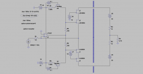
Hello All,
Thank you Ian for you post. Please find attached the schematic for a complementary symmetry precision rectifier [CSPR] which uses JFETs therein as the switching elements. Please note the following:
1. CSPR is to the left of the of $ sign vertical barrier.
2. To the right of the $ sign barrier is a load to [CSPR] which is used here to reconstitute the rectified music pulses so as to give us the opportunity to analyze its FFT performance [found THD = 0.02%] .
3. The 10 Ohm resistors in the drain circuits of the cascode JFETs sense idle bias [~300 uA], and enable visualizing the resultant pulse currents and voltages.
4. I am not sure if the encircled spice directive worked as you requested in your post.
I'll locate the schematic's [.asc] file and post it.
Best
Anton
Attachments
- Home
- Amplifiers
- Solid State
- The Blomley Class B amplifier