OK, here's where things get off the tracks. For reference see Frequently Asked Questions which also answers Ed's question about 1 acoustic Watt (109dB SPL/1M).
We know that a farfield SPL of x will require a nearfield acoustic power of y, independent of area, sensitivity, electrical power, etc. Power varies with the product of the square of area and the square of velocity, which is itself linearly proportional to volume displacement.
Changing from one driver to four, we have four times the area, so for the same acoustic power we would need 1/4 the velocity (equivalent to saying 1/4 the excursion).
Thanks for an interesting puzzle,
Chris
Last edited:
ED:re, what you do for a living....
How much amlifier power do you put into a typical install?
How many acoustic watts is in a typical system you put together?
jn
How much amlifier power do you put into a typical install?
How many acoustic watts is in a typical system you put together?
jn
The Neumann pole, also called F4, is a practical realisation of the limitations of the cutter. Take a look below - I didn't write any of it, so if it is a fabrication... not, it wasn't me and I am happy to give the credit to whom it belongs.
That pole is a practical reality BUT not in the spec. As I pointed out there are different implementations that meet a reasonable tolerance at 20 KHz. Given that the curve was defined in 1954 there was little consideration above 20 KHz. Neuman and Westrex have similar implementations (Westrex actually invented the current stereo format) but they are not the same. I believe there are others as well all lost in the mists of time. Here is a history (not sure about some of the claims since no original sources are mentioned) RIAA Curve: The 1954 Turntable Equalization Standard That Still Matters but it references several different "f4"s. The DMM stuff seems odd to me since that was a very late development. The assortment of playback curves in the mono era ensured no one got it right consistently.
If you are concerned about phase response then that HF pole will be important. If you are concerned about feedback avoid records; the typical cutterhead has 20+ dB of midband feedback to be useable. The actual system response on the cutter side it setup using diffraction patterns on the disc, not based on any playback response.
Somehow this feels like debating different dial phones, Automatic Electric vs. Western Electric vs. Stromberg Carlson. Exceptionally pointless today. This knowledge is as useful and my knowledge of the inner workings of an automatic card punch or 10" computer tape drive.
ie -12dB, aka 62.5mW.
Yes, this is a better approach. The composite driver gains 6dB sensitivity over a single driver, so the composite needs -6dB of the single's electrical power for the target SPL. Each of the four individuals gets -6dB of that. Electrical to acoustical conversion efficiency hasn't changed (note: this may be where some confusion is introduced) for an individual driver. Excursion varies with the square root of acoustical power, and therefore electrical power, so for -12dB electrical power, excursion is -6dB (1/4).
All good fortune,
Chris
Last edited:
Changing from one driver to four, we have four times the area, so for the same acoustic power we would need 1/4 the velocity (equivalent to saying 1/4 the excursion).
Thanks for an interesting puzzle,
Chris
I agree in part with the answer, but I asked for the answer in mm at the target 90dB SPL.
So how many mm?
Last edited:
1/4 of the excursion with a single driver.
I think there are two tricky parts. First is that an individual driver doesn't gain conversion efficiency by being part of the composite; it sees pretty much the same radiation impedance either way. Second, and maybe more pertinent, is that acoustic power out varies with the square of excursion.
Because these are not obviously intuitive, intuitive thinkers like you and me are probably better off starting from an acoustic power target, rather than the more abstract farfield SPL, although they're directly related.
Edit: the fundamentals above are correct-ish, but my math and conclusions are not necessarily so.
All good fortune,
Chris
Last edited:
1/4 of the excursion with a single driver.
Chris
The thing that is tricky is understanding what we get from 1 Watt of energy from the amplifier and that with four drivers we only need 1/4 Watt, or 250mW. This means that we have gained 6dB and cut back to our 90dB SPL target, which means we have also cut back our excursion [Edit: and our needed volume displacement].
Question 1. So by going back from 1 Watt to a 1/4 Watt, how much have we cut back on the excursion?
Question 2. Then since that is shared by four drivers, is it then divided by four - is the excursion divided by four?
It's not a puzzle, back i around 2003-4 I realised this has serious real world implications (and also reveals what driver designers do, but that is another story).
So, I decided to show an actual sample below, which is a 2-1/2-Way speaker system. The top three drivers, the tweeter in the centre, forms a point source (get the crossover right, of course). But these two drivers here are in series. The bottom drivers, those two are also in series. Each 'leg' is thus 16 Ohm and when they are in parallel below a few hundred Hertz, they are series-parallel and hence a nominal 8 Ohm load on the amplifier.
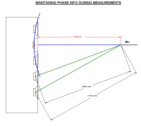
[Edit: We can see the bottom drivers are used to fill in the diffraction loss of the box and the gain at LF is real and relied upon here.]
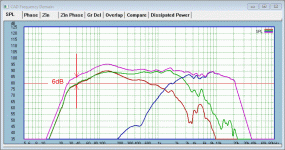
These drivers are rated at 88dB/W/1M and yet, look what is happening? Yes, that 6dB is quite for real. If the crossovers component, low passes, were removed, that 6dB could continue right up to several KHz
I am dying to tell you the answer, but in truth, I would much prefer somebody to post it, and you are oh-so-close!
Chris, please look at the two questions above. Remember that a single driver needed to produce an 8mm peak-to-peak excursion, so taking into account cutting back 6dB to our target and then dividing by four drivers is how many mm?
That number is significant, because of added headroom, but mostly because excursion-related distortion mechanisms like FFM and non-linear surround radiations will be reduced massively. Near-still cones are good all around.
Cheers, Joe
Attachments
Last edited:
Chris,
Yes an acoustic watt at 1M should produce 109 dB SPL. Joe almost got that mentioning a .25% efficiency loudspeaker producing 82 dB. (400 watts input would be plus 26 dB of power resulting in one acoustic watt yielding 108 dB SPL.)
Two identical loudspeakers mounted on the same baffle as a single unit when wired in parallel should produce 6 dB more output than a single unit. Although you can get close to that, it is not quite perfect. However the assumption that you only double the current draw is incorrect. The mechanical impedance of each driver drops. As it is the mechanical impedance that produces the sound, the result is a smaller drop in the total impedance. (Each driver is loading the other a bit.)
When you connect four drivers in series parallel the only input power increase is from the drop in mechanical impedance. Otherwise you could continue to series parallel loudspeakers to create a perpetual motion machine.
As to Joe’s post he is beginning to show a line array. The cool thing about that is that as the source becomes larger, the sound field does not drop off by the square of distance until you get farther out.
Last edited:
OK, here's where things get off the tracks. For reference see
Changing from one driver to four, we have four times the area, so for the same acoustic power we would need 1/4 the velocity (equivalent to saying 1/4 the excursion).
Thanks for an interesting puzzle,
Chris
OMG, so just bringing my rapidly aging logic to bare on the problem turned out a correct answer? at least in our opinion, removed from the rest of the gymnastics, the output of each driver for each watt remains unchanged, it is just divied up among whatever number of drivers there are. thank you for at least putting my mind at ease that if i'm wrong, its not just me 🙂. of course there are many other factors wrt what power arrives at the ears, due to enclosure, other boundaries, placement etc, but that is not relevant to the problem as written. the sensitivity for the system remains 1w for 90dB at 1m and +/-4mm excursion (1W for 1 driver, 500mW +/-2mm for 2, 250mW and +/-1mm for 4 (Joes example)) and all put out 90dB at 1M if you only feed them 1W, without getting into the nitty gritty of losses.
Last edited:
Starting from the point of each driver in the four driver composite making 1/4 of the acoustic power output, and excursion varying with the square root of acoustic power, each driver would make sqrt 1/4 = 1/2 the excursion of a single driver. This conflicts with my maths above, so at least one, and probably both, are wrong. Too late at night to see what's what.
Edit: I know the answer you want is either 1/8 or (more likely) 1/16, but we're not there yet. Keep the Faith.
Edit again: this is all wrong. Tomorrow.
Thanks again for the puzzle,
Chris
Edit: I know the answer you want is either 1/8 or (more likely) 1/16, but we're not there yet. Keep the Faith.
Edit again: this is all wrong. Tomorrow.
Thanks again for the puzzle,
Chris
Last edited:
Did you mean to say point source, because I don't understand? You've defined the destination so far, but not the source, where it seems as though you've spaced the upper woofers apart to time align them.The top three drivers, the tweeter in the centre, forms a point source (get the crossover right, of course).
Joe Rasmussen said:That number is significant, because of added headroom, but mostly because excursion-related distortion mechanisms like FFM and non-linear surround radiations will be reduced massively. Near-still cones are good all around.
Yes, its important, if we were talking about distortion, but we arent. its nothing but an interesting aside, if we are talking about the problem.
Edit: I know the answer you want is either 1/8 or (more likely) 1/16, but we're not there yet. Keep the Faith.
Edit again: this is all wrong. Tomorrow.
Thanks again for the puzzle,
Chris
Think about this way: If 1000mW gets you 8mm of peak excursion, how much excursion would you get with 62.5mW. Maybe that might help.
There are two ways of solving it, and 1000mW versus 62.5mW is one of them. When you know the answer, then slap your forehead and see how ridiculously easy it is to overthink/overlook something obvious. Please note again, it had me going to for a while... the human mind is a funny thing.
[Edit: There are three ways.]
Did you mean to say point source...
Yes, true, but that becomes a different issue.
Yes, its important, if we were talking about distortion, but we arent. its nothing but an interesting aside, if we are talking about the problem.
BUT! We are talking about distortion, so it is more than just an exercise. It has two benefits, lower distortion, and higher efficiency along with higher voltage sensitivity. That gain in 6dB is a big deal.
Like I said, line sources have a real benefit and yes, they do lower distortion.
Last edited:
"Think about this way: If 1000mW gets you 8mm of peak excursion, how much excursion would you get with 62.5mW. Maybe that might help."
An acoustic power ratio of 16 is an excursion ratio of 4. Keep getting the same answer. If we're really lucky, Joe D'Appolito won't see this and answer it with a brilliantly simple two sentence explanation.
Chris
An acoustic power ratio of 16 is an excursion ratio of 4. Keep getting the same answer. If we're really lucky, Joe D'Appolito won't see this and answer it with a brilliantly simple two sentence explanation.
Chris
I'm not arguing it lowers distortion. I agree it does, but i'm unclear what that has to do with this, other than by using 4 drivers and limiting the excursion required for the same output, you keep the drivers operating in a more linear range of excursion ie. it is relevant as a result, but it has nothing to do with how we got there. That is 'putting the horse before the cart' so to speak.
Very basic, when you are at a point from two sound sources where they both contribute equal energy the level increases by 3 dB if the signals are not correlated. If they are correlated and in phase the increase is 6 dB.
However if they are in phase at your location there are other positions where they are out of phase and cancel. That is how a line array becomes directional.
The rule of thumb for drivers to work for a line array is that they must be close to each other, either a half or quarter wavelength depending on your expert. (The difference is really on what you consider to be the acoustic source/center.)
Last edited:
Very basic, when you are at a point from two sound sources where they both contribute equal energy the level increases by 3 dB if the signals are not correlated. If they are correlated and in phase the increase is 6 dB.
However if they are in phase at your location there are other positions where they are out of phase and cancel. That is how a line array becomes directional.
This makes sense, but again, it's not like there is any more energy, it is just correlated in space and time, so each pressure cycle adds more completely for a given position; right? rather than fighting itself and adding/cancelling etc in the acoustic domain.
JN,
Just did a small 7,000 seat field house. We took out 12 stereo 165 watt per channel 8 ohm amplifiers from the old system. Put in about 60,000 watts of amplifiers. Did need a bit more AC mains supply.
I expect 20 dB of dynamic range in use and compliance with the OSHA standards for two hours of exposure. (100 dB for 2 hours.) as the system isn’t really at maximum level for the entire game, the exposure is less. However one secret is that the crowd noise can be 10 dB louder than the sound system. So exposure to that should be less than half an hour.
For a 70,000 seat outdoor venue we can use as much as 250,000 watts of peak power. I did one city arena where they had to draw power from two substations. Fortunately the electrical design engineer in charge did understand when I explained we had to run a neutral between the two points of entry and derive the safety ground point from the center of that rather heavy gauge wire. This was grounded by using a ring around the venue with multiple ground rods to make up for the high ground resistance in that area, as it was virtually all “fill.” The electrical contractor offered to save some money by skipping the link wire and just tapping each power entry into the closest part of the ring. I must have written the explanation of the issue well, because the cost savings was soundly rejected.
Last edited:
This makes sense, but again, it's not like there is any more energy, it is just correlated in space and time, so each pressure cycle adds more completely for a given position; right? rather than fighting itself and adding/cancelling etc in the acoustic domain.
I think you have got it, but the language being used around here reminds me of the hypothetical problem of if we meet an alien species, how do we communicate without common understandings?
Jan,
The amplifier may be putting out the same voltage, however the load impedance drops and the amplifier produces more current. Thus the power to the loudspeakers is increased.
Just for fun hook up two drivers to an impedance meter and see how it changes if you use different arrangements of the drivers. Try face to face, next to each other line array style and for the interesting bit both face down on a bench top.
If you really want interesting try and measure the impedance of a loudspeakers horn loaded compression driver outdoors.
Joe used 4 drivers in series and // so the impedance remained the same.
Jan
- Home
- Member Areas
- The Lounge
- The Black Hole......