If the sensitivity is 90dB/W for 1 speaker element then series-paralleling 4 speakers... doesn't suddenly change the sensitivity from 90 to 96 dB/W, start over again Joe. 😉
Have you ever done it?
I bet you haven't.
And what is your answer then, what will the excursion be reduced to?
This is a legit question, please, how many millimeters peak-to-peak?
thus you will not get the full theoretical 6 dB boost. It will more likely be around 4.5 dB.
Nope. It will be very close indeed to 6dB, in the same way that crossovers that sum at -6dB will be flat. So the tweeter will be -6dB and the Midrange will be -6dB, and yet will sum flat. Butterworth sum at -3dB because there is 90 degrees phase shift and hence only sum every alternative quarter, and hence 'sum-cancel-sum-cancel' and hence you do not get the full vector summing.
BTW, there are so many programs out there, find one and do it. It works in theory and in practice.
PS: Take two drivers and put in parallel, you will also see 6dB of gain. But here the doubling of power to a nominal 2 Watt (4 Ohm load) will give you 3dB and you get 3dB for free. Go the whole hog, four drivers in series-parallel, you get the full 6dB. Please trust me on this... or actually do it, or even simulate it, OK?
Last edited:
Excuse me, as this isnt my area at all, speaker building is nowhere near something I would call a skill of mine as yet and i'm feeling my way intuitively. so i'm probably messing this up in some way and I wont be writing the equation to your standards.
But ... don't the drivers still require the same power for the same output?
in my mind, to output 96dB, discounting mechanical losses you would need to put the same 1W across each of the 4 drivers, so 4W total, not 1W, right? if you only put 1W across the 4, the excursion required would be reduced for each individual driver to make up the same total pressure (250mW for 1/4 of the excursion and 84dB a piece, x 4. So for example your 1W for 1 x driver at 8mm pk-pk, or +/-4mm, becomes 4 drivers at 250mW each, producing 2mm peak to peak, or +/-1mm each), but the total power required to give the same pressure level would be the same 1W for 90dB. for a '6dB' increase, we need 4W total, 1W each and 8mm peak to peak on 4 drivers.
if i'm wrong, where does this efficiency come from?
Last edited:
Joe, you know the answer to your question, so why have you asked it.. what is your point?
I wonder this also ...
Gotcha!
What does this prove?
I think you all know, and it is delicious.
So we go from 8mm peak-to-peak and down to a lower value. Is it a quarter of that value?
What does this prove?
I think you all know, and it is delicious.
So we go from 8mm peak-to-peak and down to a lower value. Is it a quarter of that value?
But ... don't the drivers still require the same power for the same output?
if i'm wrong, where does this efficiency come from?
I give you credit, at least you are trying. The answer is both tricky and simple at the same time. I love the expression "it is a riddle wrapped in a mystery inside an enigma."
Think of surface area and the impedance of air. No, we don't need to get into fancy maths about the impedance of air, just understanding the fundamentals is right.
I first looked at this back around 2004 and thought to myself, WOW! Is this really true? And the answer was 'yes.'
Joe, i've given my answer petty specifically. Just speak like a normal person please. i'm sure I could get around, google it, simulate it and maybe have an epiphany, but off the cuff ive already answered.
yes, the mechanical resistance/impedance of air is going to be reduced by doubling the surface, but you still need to double the power to achieve that, or the same power, from 2 sources, dont you?.
but again, what is the point? maybe i'll learn something here, but to what end?
yes, the mechanical resistance/impedance of air is going to be reduced by doubling the surface, but you still need to double the power to achieve that, or the same power, from 2 sources, dont you?.
but again, what is the point? maybe i'll learn something here, but to what end?
Last edited:
Suppose I can test it out when i'm doing my driver measurements during the week; if only this QLD rain/humidity would stop!! are you saying that because the effective electrical impedance is halved, at the same time as the acoustic impedance is halved that there is a doubling for free somehow? i'm not sure how that works, at least in my head, late at night. Not sure i'd e doing myself any favors to continue punishing my brain this close to bed time.
Last edited:
Suppose I can test it out when i'm doing my driver measurements during the week; if only this QLD rain/humidity would stop!!
That's actually a really good idea!
Please don't try it at 40 Hertz, it works up to fairly high frequencies, it has to do with wavelengths of course, or you won't get vector summing. But adjacent drivers on the same panel and it works up to near 10KHz.
Good luck on the weather, been there! 😀
I did not realise you were in Queensland. It's only State-Of-Origin time that I feel some animosity - others here will not have a clue what that means. At least Bathurst went to a Melbournite and not an Aucklandite. 😀
PS: If you can do it at 40 Hertz, kudos to you.
Last edited:
What do you get if you put them across the room and measure between them at 10kHz? (since we're having question time.)But adjacent drivers on the same panel and it works up to near 10KHz.
What do you get if you put them across the room and measure between them at 10kHz?
Interference pattern.
Yes, i'm up in Bauple State forest. QLDer by birth, but was living in sydney up till before the pandemic locked me in. lots of room for outdoorsy measurements and aging and tolerant neighbours, but it's wet, humid and teeming with cicadas and frogs at the moment!! enough to make even windowed measurements problematic. fine enough for this though I would imagine and if I give the frogs a big enough warning shot across the bow with the speakers; they tend to shut up for a bit 😀
Definitely still QLDer for state of origin purposes.
Definitely still QLDer for state of origin purposes.
Yes, well I didn't hear that last bit but cicadas are cool. As a child I used to get around in summer wearing their shells. Better frogs than toads.
Hey Guys, isn't time to go to bed?
IG, you doing that measurement is going to be really cool, trust me!
Goodnight!
IG, you doing that measurement is going to be really cool, trust me!
Goodnight!
I was thinking about a single measurement like you did.Interference pattern.
(Goodnight.)
Yes, well I didn't hear that last bit but cicadas are cool. As a child I used to get around in summer wearing their shells. Better frogs than toads.
Yes, cicadas are very cool animals; was always fascinated by them as a kid too, but OMG they are going OFF at the moment. About 3-4 months of the year they are constant up here, like deafening, ive never hear anything like it. Couldn't agree more re frogs. we get heaps of different types and toads are all but eradicated. plenty of birdlife/parrots of many types including gang gang (black cockatoos), birds of prey, taipans, brown snakes, wallabies. quite a change from Marrickville.
Hey Guys, isn't time to go to bed?
IG, you doing that measurement is going to be really cool, trust me!
Goodnight!
ok, No promises other than I will try and achieve it when nature allows and I do need to be doing measurements anyway. I was thinking about knocking up a quick and dirty MTM vocal/centre channel, so perhaps I wont even have to do a rough baffle just for this test, but it is a busy time of year. i'll update when I have something.
RE MP3/AAC etc. The lessons about what matters and what does not are right there. We have not learned how to understand them. If that much can be discarded and its that good we should look at what remains to understand our hearing. Reducing hearing to a single dimension is clearly not enough. This book has been very enlightening on the subject https://www.amazon.com/gp/product/B08RHGZBT2/ref=kinw_myk_ro_title
Took a look at the book.
Regarding what I have said in the past about learning what to listen for, looks like it was consistent with what the book has to say about it. Why so many doubters and deniers at the time is more the puzzle for me. Why the refusal to even try learning. Oh well, that's probably explained in some other book.
Joe, how many Tuborg's did you cram on your BD.. you aren't wrong per se to get +6 dB boost under certain conditions for your 4 speaker arrangement, but that's only valid with a specific loudspeaker configuration and/or other additional variables, but you didn't mention initially anything more specific than the "sealed box" and the "4 series/parallel" configuration so therefore it per automatically disqualify your typically toxic "I won and the rest of you are feeble-minded bullies!" BS card you, as so many times before, so eloquently again pulled out of your chocolate donut.
Anyone can pull an equally rotten Joe-style stunt by stating cryptically "I can get +X dB boost, but with only 3 drivers" and then add some further word salad obfuscation "but I am going do this with 2 drivers to get the same +X dB" (while in some cases it isn't necessary to use more than one driver to get a bass boost, but it adds a layer of deception), now I'm not asking for any answer but Joe should know too that this is also true as there are a few other ways to boost the bass output, such as for example placing a speaker against one wall relative to free space placement adds +6 dB, other speaker and room placements combinations yields other figures, and then we have horns, TL, BR etc., but again, Joe never disclosed what kind of apple-to-apple or apple-to-orange comparison was discussed at hand, so therefore renders Joe's point void and null.
It's shame and such a dishonest discourse where as usually Joe couldn't uphold his self-moral to a higher standard and put all the cards on the table so any meaningful discussion is possible, but don't worry your sidekick rayma will be soon in soothing and give you a "well done bro" tap on your back.
btw, I can depict your Danish alter ego Joe...
For those who don't understand the Danish in the pic.. Joe's bum friend asks him Hey Joe, can you tell me, when does a Tuborg taste the best? whereby Joe naturally answers Every time! 😀
Do you still understand and speak Danish Joe?
Attachments

yes, i'm still rather suspicious (I mean come on, he used the words 'trust me'), but I dont have the energy. if the boost is simply coming from 2, or 4 drivers in half space, then yes, its dubious. and it is not free, or separate just redirected energy that is not explicitly contained in the 1W at 1M sensitivity spec for the driver. it is there, all the same; it is just not mentioned as it would typically not be directed towards the mic. i'm unsure of exactly what its in aid of, either. if it turns out; what relevance does it even have? it isnt a signal that wasn't expected; it has just been redirected towards a new end. Anyway, i'm done for the night and I honestly couldn't give a ****; since if that's how it pans out, it would only illustrate my earlier point.
Last edited:
I feel honoured, but I don't think anybody needs your explanation.Hans, I was going to let you off the hook, but I have changed mind. You deserve this...
When the following explanation is made clear, will you overcome your arrogance and be a man enough to apologise?
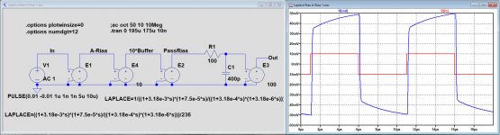
You don't seem to know how an Inverse-RIAA is used, so I shall explain in no uncertain terms:
If only you had said from the beginning that your Riaa amp was a Riaa amp + 3.18usec Neumann zero, it would have saved quite some time.
That was the reason in the first place why I asked for the anti Riaa network that you didn't want to give.
And displaying a picture without axes didn't make things that much easier.
To get at nice square wave like you showed with a Neumann zero out of your 4Mhz preamp, you will need an anti Riaa circuit with a 2.55usec pole, not quite that simple to tune. With a 3.18usec pole you will get the image below.
And indeed, now for a Riaa preamp + Neumann zero with 40dB gain@1Khz, you only need an input signal of +/-10mV at the anti Riaa stage to get a +/50mV output from the Riaa preamp.
Without this Neumann Zero I would have been impressed, but now it is a mystery to me why you showed this square wave output outside the Riaa range as a prove of your skills.
Hans
.
Attachments
- Home
- Member Areas
- The Lounge
- The Black Hole......