But you still read his post?That's OK, you were already on mine.
Howie,
In the theme of great minds think alike, we should consider insane folks flock together.
I though about the same thing with transmitter tubes. Stopped by the filament current requirements.
Recently cleaned out a transmitter shack. Got a few nice tubes up to the 15000 version. What was interesting about the spare tubes is that all three of the transmitter were solid state! For the uninitiated, an FM transmitter, backup and an add-on digital subcarrier one.
Anyone interested in a 2,000 watt US FM commercial transmitter, do let me know.
Howie, thanks for helping me distribute useful parts from the main transmitter. Two NPR stations now have spares. What is interesting is hams have in the past bought 20 KW tubes! Also I broke up one of the very obsolete CBS audio processors and later found folks bought them whole and still used them.
It will be interesting to see what commercial FM transmitter modules end up getting used for when sold on eBay.
Hi Ed,
I would always rather see old equipment put to good use rather than end up in a landfill, good on ya for finding homes for some of it!
The filament requirements for the 8877 are pretty stout at 10.5 A @ 5 V for sure, but what really kills the idea for me is finding a plate transformer for a beast with two of them...although there is likely an old AM transmitter out there with a modulation xfmr that would work.
But...these days you can get 2 kilowatts in two RUs, and the 8877 being a ceramic triode doesn't even have a nice glow, and isn't that why people like tube amps? 😉😉
Cheers & 73,
Howie / WA4PSC
Ed, what about the JLH1969 ? (mine, still on duty during wintertime 😀 )Of course you would be not looking at an audio power amplifier that uses output transistors as poor as that part, unless designed for nostalgia, cheapness or of course incompetence.
JLH 10 Watt class A amplifier
For Howie and any RF inclined participant
http://www.dc9dz.de/downloads/tsunami_en.pdf
George
Looking forward to it.As for me, they will be published on paper and PDF format. They will be peer-reviewed by a 'panel' that includes three physicists and several with trained with maths and engineering backgrounds - and they will be named on the paper.
In the meanwhile, why not just build a simple prototype of amp+woofer in small CB and send it over to an experienced test engineer to check the damping claim?
I'd volunteer but can see why it's not going to happen (note that I retired from speaker design, not commercial or other interests any more, and I would even sign an NDA nonetheless).
OK, Plan B: Do a little presentation locally with such a setup and allow a skilled member of the audience which is registered here to do the tap test to check, maybe even record it with a mobile recorder, whether the claimed damping is really there or not.
If you really have something going on there, despite all sane reasoning that the idea will not work for reasons, basically first principles, I've explained (and I'm -- rather: was -- a hands-on guy, not an arm-chair theorist) you have to get out of your comfort zone and stop the childish whining... sorry for having to be that blunt.
I for one have no problem to stand corrected, just in case.
Just adding, a current driven speaker would ring if disturbed but Joe's zobel treated speakers would not, as they are still damped by a low source impedance. Whether that matters in context of the discussion I can't say.
Actually, as we have seen much evidence of it here, this is anti-social media.
I only asked you a question, I understand if you don't want to answer because the information is proprietary but please say as much and I will stop asking.
Ed, what about the JLH1969 ? (mine, still on duty during wintertime 😀 )
JLH 10 Watt class A amplifier
For Howie and any RF inclined participant
http://www.dc9dz.de/downloads/tsunami_en.pdf
George
George,
That is built late enough the 2N3055 is not a hometaxial version but a modern one with enough gain bandwidth to cover the audio bandwidth. The transistor should more properly be labeled a 2N3055A! Also if I understand the amplifier it used a constant current source as half of the output circuit. Thus eliminated the huge current gain swings of the 2N3055.
I may actually have somewhere an RCA hometaxial unit. If I find it the gain bandwidth at 3 amps should be interesting.
As to your transmitter cite, where can a ham use more than 2,000 watts? The U.S. limit is 1,500 watts last time I paid attention. Even less in most European countries.
Last edited:
Isn’t there a guy somewhere on the forum that spent an insane amount of money using a big RF transmitter tube to make a big class A amp?
I think he just about remortgaged his house or something at that level.
I think he just about remortgaged his house or something at that level.
When you add a damping cell across the amp output it's not pure current drive anymore even if the amp core is. It's mixed impedance drive and yes, this works (tap test will show significant damping).Just adding, a current driven speaker would ring if disturbed but Joe's zobel treated speakers would not, as they are still damped by a low source impedance. Whether that matters in context of the discussion I can't say.
I've proposed this many times: for a given woofer in a given situation (CB or ported or whatever) one can find an optimum drive impedance profile vs. frequency. Almost always it's low/medium Z around and below resonance and high Z elsewhere.
There was a saying in Journalism, "If you can't explain it simply, you don't understand it!"
I can see what this does, even if I'd prefer to see some component values to make it easier:
I've modelled this sort of thing, and it's quite good:
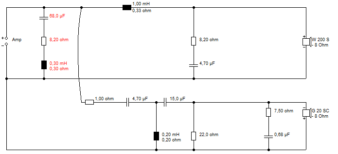
Then I used Jeff Bagby's ideal filter values and even the notorious Series crossover fell into place:
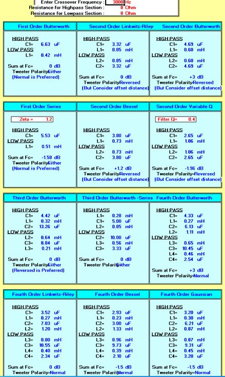
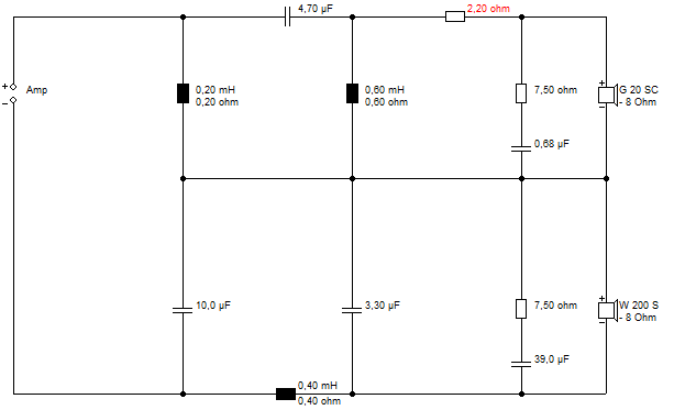
That one even has a bit of invisible bafflestep built in, because it's a high inductance woofer. If I lost the Zobels with low inductance woofers, I suppose I'd end up doing a 2.5 way.
I can see what this does, even if I'd prefer to see some component values to make it easier:
I've modelled this sort of thing, and it's quite good:
Then I used Jeff Bagby's ideal filter values and even the notorious Series crossover fell into place:
That one even has a bit of invisible bafflestep built in, because it's a high inductance woofer. If I lost the Zobels with low inductance woofers, I suppose I'd end up doing a 2.5 way.
When you add a damping cell across the amp output it's not pure current drive anymore even if the amp core is. It's mixed impedance drive and yes, this works (tap test will show significant damping).
I've proposed this many times: for a given woofer in a given situation (CB or ported or whatever) one can find an optimum drive impedance profile vs. frequency. Almost always it's low/medium Z around and below resonance and high Z elsewhere.
I wasn't sure whether Joe is using current drive or not (he seemed to be saying it's no longer necessary with his developments), but now I remember one of the touted advantages of the zobels is that you get the same response in voltage or current drive. And yes I am aware that the zobels provide a current path for re-entrant distortion.
@steve
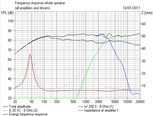
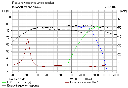
I’m not a speaker guy (it’s black magic to me but I do wish speaker designers would keep impedance dips to no lower than 3 ohms) but the LF response seems to drop off quite early. Could you improve it by changing the LF resonance peak? Might of course mean a larger cab.
I’m not a speaker guy (it’s black magic to me but I do wish speaker designers would keep impedance dips to no lower than 3 ohms) but the LF response seems to drop off quite early. Could you improve it by changing the LF resonance peak? Might of course mean a larger cab.
I can accept that produced sound is perhaps somewhat similar to current driven driver. However, technical explanation on how the driver works similarly to a current driven one leaves a lot to be desired.
@steve
I’m not a speaker guy (it’s black magic to me but I do wish speaker designers would keep impedance dips to no lower than 3 ohms) but the LF response seems to drop off quite early. Could you improve it by changing the LF resonance peak? Might of course mean a larger cab.
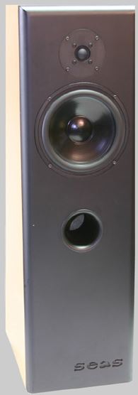
People lose far too much sleep about bass response. Put it by a wall and it will be much bassier. And as I said, the speaker has built-in inductance, so sounds bassy anyway. The high-inductance SEAS A26 midbass needs no added coil whatsoever.
SEAS The Art Of Sound Perfection
In fact the above example will work well with a high-impedance SET amp. The added amplifier output resistance actually deepens the bass response.
Doesn't work so well with reflex.
Right Ed. All correct regarding the JLH1969 amp.George,
That is built late enough
In Europe at HF bands, limit is 400W (100W for 6m band).
This is peak envelope power supplied to the antenna by the transmitter. It is measured at the antenna, therefore impedance mismatch and any power loss has to be taken into account, leading to a choice of higher power amps, usually up to 1kW.
This Bulgarian brand has made a hit across Europe (Swetlana 4CX**** tubes)
Products Misc | ACOM
George
Please Hans, but you are a Johny-come-lately here.
I DID post measurements!
Waste of time.
I DID posts maths!
Seems those who looked (in fact they did not), were numbers challenged.
I DID post graphs!
This was several rather stunning graphs. If only you had seen them, maybe your attitude would have been different. But you don't give me any confidence with your tone. It is condescending and demeaning.
I DID IT THREE TIMES!
So please, can you give me enough confidence to do it a FOURTH TIME!
Over to you.
Johny-came-early and refers to where you came in at #7382
- The only time you published graphs since then was to show that placing an 8R resistor in par. to a speaker changes the overall impedance as seen from the amp with speaker only.
Something this basic is primary school math.
But especially the added comment that this would result in measurable distortion reduction made me ask for measurements to prove this.
Request not granted.
- With measurements I refer to measurements done by yourself.
The only time you linked to measurements was in #7450.
However these were Pavel's and not yours and unsurprisingly completely in line with ESA's book, other people's feathers so to say and definitely no new information, but quite useful as a start for trying to make the next step.
And that next step is exactly what I was expecting but fail to see so far.
So when you still don't want to disclose, that's fine, but why posting in that case and not waiting until the PDF you refer to has been published?
This is pushing hot air.
As for me, they will be published on paper and PDF format. They will be peer-reviewed by a 'panel' that includes three physicists and several with trained with maths and engineering backgrounds - and they will be named on the paper.
I'm looking forward to it with an open mind.
Hans
- Home
- Member Areas
- The Lounge
- The Black Hole......