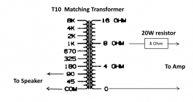
jjasniew said:To my ears, the small experiment using the line matching transformer backward shows tremendous listening potential to this idea. The amplifier voltage output is converted to a current by a resistor. That current goes into a transformer winding and on the other side, a smaller current comes out of a high impedance source, driving a Wideband speaker.
My speakers are WAWs, so there's no resonance at Fs to wonder about; the wide-bands are crossed well above that. The woofers are run conventionally, with the full damping factor provided by the amplifier's ordinary low-Z output. Unsure why anyone would want to give this up by running woofers from a current source, but hey.

The difference I hear I'd describe as similar to going to a better DAC with more stable clocks - a soundtsage image focus improvement. I cant believe how easy it was to try and that I had the parts just laying around...
Now excuse me while I fall into Ella's very live sounding voice image back there on "Sweet Georgia Brown" - on an internet stream from WBGO - it's none the less fantastic to my morning ears. Cant wait to try it on the F15's.
I think you may be redisovering what we old Radio Engineers call Norton Thevenin Equivalents.
There is really no difference between Current and Voltage Amplifiers except the implementation. The resistor is linearising the load seen by the amplifier. Thus lower distortion.
I used to notice that adding an 8 ohm resistor to the loudspeakers in a boom box produced a smoother sound. But less efficient of course. Adding resistance to a loudspeaker extends bandwidth.
In fact amps and loads can be designed for maximum power transfer or maximum energetic efficiency. If valve amps sometimes sound better, it is because they are extremely fast devices. Transistors are relatively sluggish, so can't quite keep up with feedback at high frequency.
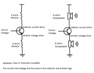
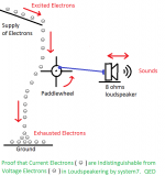
I add a couple of humourous images to lighten things up.
Attachments
If valve amps sometimes sound better, it is because they are extremely fast devices. Transistors are relatively sluggish, so can't quite keep up with feedback at high frequency
Whaaaaat? Feedback is once again eating it’s own tail?
...If valve amps sometimes sound better, it is because they are extremely fast devices. Transistors are relatively sluggish, so can't quite keep up with feedback at high frequency...
I believe you should consider looking deeper into this statement, it has no merit in reality...this has been debunked on a regular schedule here...
Cheers!
Howie
If valve amps sometimes sound better, it is because they are extremely fast devices. Transistors are relatively sluggish, so can't quite keep up with feedback at high frequency.
Hopeless. This argument might have been valid 60 years ago. Are you a circuit designer?
If valve amps sometimes sound better, it is because they are extremely fast devices. Transistors are relatively sluggish, so can't quite keep up with feedback at high frequency.
The post by jjasniew is "Far out", but Your post is complete nonsense.
I'm wondering: Do you actually mean this and understand what you are saying?
😕
“ If valve amps sometimes sound better, it is because they are extremely fast devices. Transistors are relatively sluggish, so can't quite keep up with feedback at high frequency.”
@Steve I assume this is parody, right? 😀
@Steve I assume this is parody, right? 😀
Whaaaaat? Feedback is once again eating it’s own tail?
There's a Greek myth about stones and a mountain that seems rather apt at this point.
No math, no measurements no nothing to show that it makes sense to follow these ill defined roads.
Please Hans, but you are a Johny-come-lately here.
I DID post measurements!
Waste of time.
I DID posts maths!
Seems those who looked (in fact they did not), were numbers challenged.
I DID post graphs!
This was several rather stunning graphs. If only you had seen them, maybe your attitude would have been different. But you don't give me any confidence with your tone. It is condescending and demeaning.
I DID IT THREE TIMES!
So please, can you give me enough confidence to do it a FOURTH TIME!
Over to you.
As for me, they will be published on paper and PDF format. They will be peer-reviewed by a 'panel' that includes three physicists and several with trained with maths and engineering backgrounds - and they will be named on the paper.
YOU CANNOT DO SCIENCE ON SOCIAL MEDIA!
Actually, as we have seen much evidence of it here, this is anti-social media.
Last edited:
“ If valve amps sometimes sound better, it is because they are extremely fast devices. Transistors are relatively sluggish, so can't quite keep up with feedback at high frequency.”
@Steve I assume this is parody, right? 😀
I read it as a total misunderstanding. For old folks comparing the gain bandwidth of a 2N3055 (HUMOR) to a 6L6, the tube wins by orders of magnitude. Worse yet even with the drastic limits of the tube requiring an output transformer, it still could outperform a 2N3055.
Of course no one actually makes a transistor that meets the minimum requirements of the original hometaxial 2N3055. All of the transistors made for even the past several decades are much better. So anything made since the 70s would be about as fast as a 6L6, but it would be labelled a 2N3055 even though it far exceeds the original specifications.
Of course you would be not looking at an audio power amplifier that uses output transistors as poor as that part, unless designed for nostalgia, cheapness or of course incompetence.
As to the input device a 12AX7 also has better gain bandwidth than an original 741 op-amp. However the specifications even on the 741 as usually available today could exceed the tube.
Not sure I can find any currently manufactured input transistor that is slower than a 12AX7.
Of course vacuum tube amplifiers almost always have an output transformer. I actually have measured transformers that can handle frequency ranges of 20 hertz to almost 100,000 hertz. Of course with the phase shifts, I don’t know how you could use the entire bandwidth in a feedback path.
There are several issues where vacuum tube amplifiers are faster than solid state units. Mean time before failure will be much faster with vacuum tube amplifiers. Another issue would be warming up a small cold room.
Of course if we include solid state amplifiers using other than bipolar transistors then many of the parameters considered would change.
However there are still cases where vacuum tubes do work better at high frequencies!!! (Microwave Oven!) (Please do not stick your head in one to compare how they sound.)
There are several issues where vacuum tube amplifiers are faster than solid state units. Mean time before failure will be much faster with vacuum tube amplifiers. Another issue would be warming up a small cold room.
Of course, and don't forget the rate of breaking when dropped on the floor.
To my ears, the small experiment using the line matching transformer backward shows tremendous listening potential to this idea...
The difference I hear I'd describe as similar to going to a better DAC with more stable clocks - a soundstage image focus improvement. I cant believe how easy it was to try and that I had the parts just laying around...
Now excuse me while I fall into Ella's very live sounding voice image back there on "Sweet Georgia Brown" - on an internet stream from WBGO - it's none the less fantastic to my morning ears. Cant wait to try it on the F15's.
Congrats!
Ask yourself, what do you think you are hearing? You are actually hearing a reduction in critical distortion. I know precisely what you are hearing. The way you have done it is simple and effective and kudos to Esa for suggesting it and kudos to you to have done it, even if you did not do it precisely with his curve change components, the key is indeed that transformer.
But analysing why we are getting that reduction in distortion (which BTW is also measurable), the fact that it can also be achieved in another way(s), confirms what the mechanism that causes distortion, to be better understood.
In the meantime, enjoy your listening and the new insights it's giving you there.
FWIW, the key is that you are suppressing the non-linear part of the impedance of the driver which is is series the Re, the DC resistance of the voice coil. That Re is fairly stable (some thermal sensitivity, but time-constant only shows up below 20Hz), but the rest of the impedance, which I call the back-EMF impedance, is not stable and unstabilises the current of the amplifier. This is what current-drive prevents and even with a ratio of just 5:1 (which is what you are listening to), it definitely is audible. But there are other ways. The Purifi drivers do it another way again, they stabilise the actual driver itself, its inductance, a herculean task. I do it a third way, but there is no appetite here to listen to my explanation for it. So it will come out in a different way, in a paper/PDF.
Study the crossover schematic below and that is how it is done. This brings about the same kind of 5:1 improvement, but in a different way to a transformer.
The most single important component is what L2 does. The two MidBass drivers have extremely low inductance, they are in fact state-of-the-art in that respect. The inductance is even lower as the two 6.5" drivers are in series, in fact halved. The L2 inductor value swamps that inductance and its value must achieve that as well as 1st order low-pass function. The fact that the driver inductance is so low, we get near 6dB octave fall-off.
The above achieves a similar 5:1 ratio effect that you are listening to because the elements involved are very carefully chosen.
I have not touched on the high-pass to the tweeter, this is a bit more complex, but is guided by the same thinking - effectively achieving 5:1 current drive to the tweeter main in its bottom octaves of its passband.
There is only one rational explanation - the highly non-linear part of the impedance modulates the current of the amplifier. So if you have a non-linear event circa 4KHz, like a resonance, even a smallish one, this driver problem will show up on the current side of the amplifier. No ifs or buts. This corrupts the current of the amplifier and this is fed back into the driver, like a vicious merry-go-round. This is audible. Reducing this and you get the sound of current-drive, because this effect, this distortion, is suppressed. But we are finding other ways and we can keep our amplifiers. But there are signs that, if amplifier designers understand what is happening, then we get better amplifier designs. Everybody wins.
Cheers, Joe
Last edited:
...However there are still cases where vacuum tubes do work better at high frequencies!!!...
Going totally OT as I am wont to do, as a broadcast engineer I really appreciate the durability of tubes when connected to a 1000 foot (305 m) tall lightning rod...I mean antenna.
I have had an old Gates transmitter swallow an enormous lightning surge which caused an arc across the variable plate loading capacitor, and the 3000 V plate supply happily fed the arc for hours, burning the variable cap in the process...however it stayed on the air with only a buzzing noise showing something was wrong. I shut down the plate supply which extinguished the arc, and then turned it back on and it ran for days until the replacement parts came in...
I have difficulty thinking my solid state standby transmitter would have survived that event.
In a related subject I have always wanted to make a PP 8877 tube audio amplifier, those tubes have a really long linear region for a power tube. In class AB that amp should output 3 KW.
What were we talking about?
Howie
I just thought of something funny. Bill is a wolf without sheep's clothing! 😡😀🙂
.
.
Last edited:

Howie,
In the theme of great minds think alike, we should consider insane folks flock together.
I though about the same thing with transmitter tubes. Stopped by the filament current requirements.
Recently cleaned out a transmitter shack. Got a few nice tubes up to the 15000 version. What was interesting about the spare tubes is that all three of the transmitter were solid state! For the uninitiated, an FM transmitter, backup and an add-on digital subcarrier one.
Anyone interested in a 2,000 watt US FM commercial transmitter, do let me know.
Howie, thanks for helping me distribute useful parts from the main transmitter. Two NPR stations now have spares. What is interesting is hams have in the past bought 20 KW tubes! Also I broke up one of the very obsolete CBS audio processors and later found folks bought them whole and still used them.
It will be interesting to see what commercial FM transmitter modules end up getting used for when sold on eBay.
- Home
- Member Areas
- The Lounge
- The Black Hole......