IBM’s 2 nm Chip Dazzles with 50 Billion Transistors in Tiny Package - News
It never seems to stop with ever smaller dimensions.
Hans
It never seems to stop with ever smaller dimensions.
Hans
I just encountered this patent...
Sounds like they are saying it acts more as a charged transmission line rather than as a more typical charged capacitor. Looks like they didn't want to say it plainly though.
Ivor Catt’s advocates?
George
capacitor self resonant frequency; Scandals in Electromagnetic TheorySince a capacitor is a two-conductor transmission line with very low characteristic impedance, the transient impedance that it presents to a step is resistive, not reactive.
George
That is a lot of effort and time spent just to say in a vastly convoluted way that large capacitances can still have good HF performance. The point about the unnecessary cost of trillions of 100nF capacitors is interesting though. I can see why manufacturers wouldn't go out of their way to prove that customers don't need to buy more of their product.
Ivor Catt has a long history of debunking, in the main, electromagnetic concepts. As a reader of Wireless World, in 1978 he published an (infamous) article saying that displacement current was a fallacy, and derived the charging of a capacitor through a resistor by considering the capacitor as the sum of transmission lines.
That is on his site, as was the letters and ripostes furore that arose from it.
His website(s) are a real nightmare to navigate. But the short version is: debunking of electromagnetic theory as the decades pass.
That is on his site, as was the letters and ripostes furore that arose from it.
His website(s) are a real nightmare to navigate. But the short version is: debunking of electromagnetic theory as the decades pass.
I don’t fully understand the argumentation here. A large electrolytic has a SR of about let’s say 1-2 MHz for whatever reason (lead L, some internal L etc). Is Catt arguing against placing smaller capacitors in parallel to create a second self resonance frequency higher up, so that when the two are combined, you have a flatter, overall lower impedance across the two?
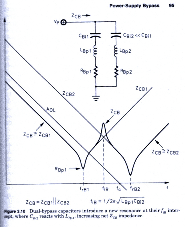
The problem arises from parasitic L from whatever cause. So you can cheerfully end up with a resonant *peak* between the two dips.
I've increasingly used surface mount construction, which means that the 0.1u or 1u decoupling caps. Usually X7R ceramic; I use 0805, and no smaller, because you can actually see them! These have almost no series L, you can put them within a mm or less of the device power pin and link it straight to the groundplane. When designing with leaded components it is very difficult to eliminate parasitic L.
I've increasingly used surface mount construction, which means that the 0.1u or 1u decoupling caps. Usually X7R ceramic; I use 0805, and no smaller, because you can actually see them! These have almost no series L, you can put them within a mm or less of the device power pin and link it straight to the groundplane. When designing with leaded components it is very difficult to eliminate parasitic L.
Have a look at the book Optimizing Op Amp Performance by Jerald Graeme of Burr-Brown. He devotes an entire chapter to supply bypass networks and unwanted resonances. Here's one of the figures in that chapter.
Click on the image to see it full size and undistorted.
Click on the image to see it full size and undistorted.
Ok - got it. I’ve seen systems with a bulk electrolytic and then 1, 0.1 and 10 nF to try to address this issue.
I use 10, 1 and 0.1 X7R in concert with electrolytics - usually 1206 or 0805
Looks like a job for a network analyzer MJ!
I use 10, 1 and 0.1 X7R in concert with electrolytics - usually 1206 or 0805
Looks like a job for a network analyzer MJ!
Last edited:
J. Graeme advocates damping resistors. I used them on the DIY project "Cedarburg" to tame the moderately-notorious AD797 oscillator opamp, and they got the job done nicely. Cedarburg is an uncommon word with more than 5 letters, so the Forum Search function is able to find it quite easily.
Graeme's books are very good.
The bypass/decoupling techniques in audio seem to be generally lagging by a few decades. It's easy enough to design a low inductance PDN and avoid anti-resonances if you don't sprinkle 0.1uF caps with traces to a via. In most cases, there is no need for multiple types of caps given the availability of high value caps in low mounted inductance packages.
The bypass/decoupling techniques in audio seem to be generally lagging by a few decades. It's easy enough to design a low inductance PDN and avoid anti-resonances if you don't sprinkle 0.1uF caps with traces to a via. In most cases, there is no need for multiple types of caps given the availability of high value caps in low mounted inductance packages.
Last edited:
A 1-100uF lytic has the right low inductance resistance range for damping a large lytic and a 100nF capacitor without needing any extra series resistance, you get lower overall supply impedance that way. However you need to know the ESR of your lytic and the approximate loop inductance.
Luckily I haven’t had any problems with AD797 - I used 22 ohm resistors in each rail and then 100 uF electrolytics and 1 uF X7R right at the opamp pins.
Ok - got it. I’ve seen systems with a bulk electrolytic and then 1, 0.1 and 10 nF to try to address this issue.
I use 10, 1 and 0.1 X7R in concert with electrolytics - usually 1206 or 0805
Looks like a job for a network analyzer MJ!
Our Gerhard did this, and got about the same results as Graeme.
That has been going on for decades that I know of, and likely much longer. Circa 1997 I was at a patent seminar where a patent was described. An engineer said to his manager "I can get a patent through on the addition of a resistor to a circuit." The manager didn't believe it, but approved the application just to see, and indeed the patent was granted. They didn't give a patent number in the seminar, but if anyone wants to look for it, the company was Schlumberger (which has lots of patents).USPTO seems to be understaffed and underfunded. Not surprising that a lot of garbage gets through. In that patent, he claims to have invented a new fundamental circuit component...
Regarding the "new fundamental circuit component" I'm reminded of the memristor. It seems like it could be a useful, practical device (in some limited circumstances), but I find it hard to consider it as "fundamental" as a resistor, capacitor or inductor. Maybe if I read about it enough times and squint enough ...
Memristor - Wikipedia
Audio Research patent 5,036,292 (granted July 1991) discloses a Decoupled Electrolytic capacitor. That shows a parallel combination of an electrolytic and a smaller (film) capacitor in parallel. In series with the electrolytic is a parallel combination of an inductor and resistor.
The idea, they say, is that the rising impedance of the inductor progressively removes the electrolytic from the circuit and just leaves the smaller (film) capacitor at high frequency. The parallel resistor is to damp the resonance of the inductor/electrolytic capacitor.
They incorporated this into a wide range of Audio Research preamps back in the day (SP9, LS2, LS3, LS22, LS25, and possibly others).
However, spice modelling using the parts values listed in the BOMs, even including parasitic L from the axial parts that Audio Research tended to use, shows that the decoupled capacitor concept is much worse that simply paralleling the electrolytic and film capacitors directly.
Perhaps that is why they abandoned the idea in later products.
IBM’s 2 nm Chip Dazzles with 50 Billion Transistors in Tiny Package - News
It never seems to stop with ever smaller dimensions.
Hans
At some point it wont go further...
That s still a prototype with 300 millions transistors per mm2, currently most advanced industrialised process is already at 100M/mm2 (albeit used exclusively for Apple).
Also, contrary to IBM s claims, it wont be faster, due to necessarely reduced voltages.
Yeah, wake me up when such a process will run in a major silicon foundry, like TSMC. IBM was always on the bleeding edge of R&D, not so much lately on product development using its R&D.
- Home
- Member Areas
- The Lounge
- The Black Hole......