🤐 All that counts is the crosstalk graph in the datasheet. 😉I have no problem understanding why dual op-amps are evil when you see the size/design on of those things(see the links the at the bottom of the page).
Yes, a bad cable can cause bad problems. Trying to drive cables with a low power op-amp is bad news. That is why they invented line drivers. With proper drive capability, almost any decent cable will work fine. Poor fitting or dirty connectors can cause rectification issues; not good. Bad crimps ( Please, solder only) don't help.
My point is a good cable is as good as it gets. Good cable is easy. Good amplifier output design is harder.
I use plain old solid copper 75 Ohm coax, foam core, 98% copper braid with generic firm seating RCA's and make them as short as possible. No difference to my Tara Labs and compared to Cardas and Monster with no difference. ( But I do love the tight as all get out Tara RCA's) Plain old coax is designed to balance the reactive parastatics for the DC to 1Ghz range. I run RG8 for speaker wire. Designed for high power under a Mhz. Beats my old Kimber 4TC. For my long balanced runs, it is some surplus Belden mic cable. Designed by cable people who are far smarter than I.
If you are trying to run 10M without proper drivers, then maybe, maybe, special wire could make a tiny theoretical difference. Good circuit/systems engineering will pay off more. I have no doubt others will disagree. Frequently a hot topic, epically from those who have paid way too much for a cable. When I can afford $50,000 amps, I will listen again and see if I change my mind. Doubt it, but I have been know to change when presented with evidence. In the mean time, I can sulk, as the store I dropped by was out of Grado's. Have to wait another day.
Hmm, honestly, all (the many...) RCA cables I've tried so far do sound different the one from the other... so much that I use my various cables to fine-tune the sound, especially the tonal character of my system.
There's no given "best material" or "best geometry" in cables. Copper can sound great both solid-core and stranded (the latter is the case of the Sommercable Classique I'm using right now), silver can be bright or not, depending on the conductor geometry, the insulation, the RCA plugs... etc. etc.
Anyway, right now I can choose between my VDH The Bay C5, my Audioquest King Cobra (arguably the best, given materials, research & ultimately cost), my VALab stranded 6N silver, and my Straightwire Encore II. Then come my few mini-RCA's ...if applicable 🙂
Last edited:
All that counts is the crosstalk graph in the datasheet. 😉
So then, looking at the crosstalk for a cheap dual opamp like the LM833, there's no problem? Better than -120dB throughout the audio bandwidth, which is better than any dual triode, better than any phono cartridge ever made, better than any analog tape recorder.
So then, looking at the crosstalk for a cheap dual opamp like the LM833, there's no problem? Better than -120dB throughout the audio bandwidth, which is better than any dual triode, better than any phono cartridge ever made, better than any analog tape recorder.
Probably. I guess that besides that, you would have to check that the dual opamp has completely separate circuitry for both channels. This would make you rock proof 😛
Actually, I'm the first to acknowledge that the single version of a given dual opamp always sounds better. That, though, doesn't mean that you should avoid like the devil a good sounding dual opamp that only exists as a dual...
In sum, since there are only a handful of really natural sounding opamps around, you shouldn't cut such a small number in half only because you avoid duals by principle. 🙂
Last edited:
Virtually all linear IC's are compromised. AND they were not designed originally for audio use in the first place. Bob Widler told me himself. Today, they are a little better, but still, it takes time and effort to sort them out.
if TI mentions it on the OPA1612 datasheet, that means that it's not the case on their older chips...and xtalk is obviously not everything.Probably. I guess that besides that, you would have to check that the dual opamp has completely separate circuitry for both channels. [..]
Actually, I'm the first to acknowledge that the single version of a given dual opamp always sounds better.
I see single/dual as balanced/unbalanced...anyway, case close on my end..I'll never use dual ever again, the center channel is shrunk down to death on all the duals I tried...maybe it doesn't come from the chip design itself, and more from the way my card uses them...whatever works! 😛
Last edited:
np, but it's mostly a lower grade OPA211 apparently: http://www.diyaudio.com/forums/solid-state/149222-burr-brown-opa1611-1612-here.html
np, but it's mostly a lower grade OPA211 apparently: http://www.diyaudio.com/forums/solid-state/149222-burr-brown-opa1611-1612-here.html
NO. It's a different opamp, with a higher current output stage (and correspondently a slightly higher input bias current). Comparing distortion graphs, it has significantly better treble distortion than the OPA211, as well.
What's more important, it sounds like an audio opamp. The OPA211, like the OPA827, sounds like "not designed exclusively with audio in mind"... i.e. more flawed 🙂
That it's cheaper than the OPA211 means nothing. Music doesn't care for that 🙂
I want to try the OPA211ID which I have, to see if it maybe sounds better than the cheaper AID.
I want to try the OPA211ID which I have, to see if it maybe sounds better than the cheaper AID.
Virtually all linear IC's are compromised. AND they were not designed originally for audio use in the first place. Bob Widler told me himself. Today, they are a little better, but still, it takes time and effort to sort them out.
I've heard someone saying that the OPA1611 would be the first opamp "with a true for audio output stage". I don't know, but it sounds great.
No...obviously. That why I keep saying that certain dual opamps are at the top of my list. 🙂if TI mentions it on the OPA1612 datasheet, that means that it's not the case on their older chips...and xtalk is obviously not everything.
BTW, the OPA2134 also has completely independent circuitry for both channels.
I reckon that the National duals must have it too..
I reckon that the National duals must have it too..
Last edited:
I was thinking that I'm too affectionate to the CS4398 sound to leave it...
So, I'd like to buy another DAC with the CS4398.
My favorite pick would be the Musiland MD10, to which I'd remove the OP275 (which must sound good tough: 4398 + 275 ...) and put an OPA1612 or AD8599 or LME49725. I'll begin to save up 😎
So, I'd like to buy another DAC with the CS4398.
My favorite pick would be the Musiland MD10, to which I'd remove the OP275 (which must sound good tough: 4398 + 275 ...) and put an OPA1612 or AD8599 or LME49725. I'll begin to save up 😎
Last edited:
Thanks for the Audio GD link.
The test circuit again is optimised for the device they are testing, not the one they are comparing against (OPA2604)
Still following this...
One for Leeperry 🙂
The OPA2604... using the "test circuit" from Audio GD ? have I got the name right.
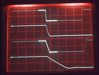
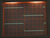
Just some quick scope shots... and just to explain what you are looking at,
the top trace is the input, the one below is the falling edge highlighted, next is the output and again the falling edge highlighted and expanded so you can see more clearly. My generator produces much faster rise/fall times than the one they use in the test 🙂 but you will see what I mean about optimising.
Output is 10volts pk pk (scope adjusted to fit four traces on) and frequency is 100khz.
1. Shows the test circuit from your link. http://www.audio-gd.com/enweb/pro/diy/OPA.htm
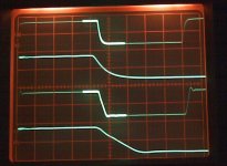
2. Shows same but with the input signal slew rate limited.
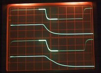
3. Shows 15pf comp to the OPA2604
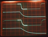
4. Shows 22pf comp to the OPA2604
5. Shows why it is important to implement correctly. This shows an NE5532 in the same circuit. A 1k input resistor has been added in series to the input 100 ohm. What you are seeing here is the generator signal (top) and the signal as distorted by the input circuitry of the NE5532 (this is NOT the output you are looking at but the signal on the 100 ohm.
Frequency here lower... 10khz
Attachments
Last edited:
I've done the impossible...
I had just got two Solen 2.2uF 250V MKP caps... but I'd never have thought I could've fitted them inside the diminutive Super Pro. 😎
That way I got rid of those two Wima MKS2 4.7uF 50V (with magnetic leads, as I discovered lately...).
I wouldn't have expected the switch from one film cap (in the signal path, 'course) to another to produce such an improvement. 😎 Bass is definitely tighter and midrange more crystalline. Tonality seems to have improved too. In short, it was entirely worth the effort!!
Last edited:
Seems like an impedance matching issue?...
5. Shows why it is important to implement correctly. This shows an NE5532 in the same circuit. A 1k input resistor has been added in series to the input 100 ohm. What you are seeing here is the generator signal (top) and the signal as distorted by the input circuitry of the NE5532 (this is NOT the output you are looking at but the signal on the 100 ohm.
Frequency here lower... 10khz
The NE5532 must sound rather bad in that circuit.Still following this...
One for Leeperry 🙂
The OPA2604... using the "test circuit" from Audio GD ? have I got the name right.
Just some quick scope shots... and just to explain what you are looking at,
the top trace is the input, the one below is the falling edge highlighted, next is the output and again the falling edge highlighted and expanded so you can see more clearly. My generator produces much faster rise/fall times than the one they use in the test 🙂 but you will see what I mean about optimising.
Output is 10volts pk pk (scope adjusted to fit four traces on) and frequency is 100khz.
1. Shows the test circuit from your link. н¨ÍøÒ³ 1
2. Shows same but with the input signal slew rate limited.
3. Shows 15pf comp to the OPA2604
4. Shows 22pf comp to the OPA2604
5. Shows why it is important to implement correctly. This shows an NE5532 in the same circuit. A 1k input resistor has been added in series to the input 100 ohm. What you are seeing here is the generator signal (top) and the signal as distorted by the input circuitry of the NE5532 (this is NOT the output you are looking at but the signal on the 100 ohm.
Frequency here lower... 10khz
BTW, do you have something to show us about any other opamp than OPA2604 and NE5532? 🙂
Last edited:
- Home
- Amplifiers
- Chip Amps
- The best sounding audio integrated opamps