And adjust the regulator's voltage set to give 24v. Yes, that's all.
It will be a very nice PCB holding rectifier, filter and regulators.
It will be a very nice PCB holding rectifier, filter and regulators.
myleftear,
If you want to use the VRDN for +/-24V without the de-noiser you can leave
out all the parts after the J3 and J4 jumpers. Also you need to make small
adjustments to the LM317/337 programming resistors since the values in the
VRDN schematics limit things to about +/-20V. (For example, increasing
R7 and R10 in the VRDN schematics here
https://www.diyaudio.com/forums/att...level-ckts-11v-20v-1-5a-de-noiser-figure1-png )
Please see https://www.ti.com/lit/ds/symlink/lm317.pdf, section 9 for more details.
Exactly.
With 220R from OUT to ADJ, 4K from ADJ to GND will give just a teeny bit less than 24V output.
With 220R from OUT to ADJ, 4K from ADJ to GND will give just a teeny bit less than 24V output.
increasing R7 and R10 in the VRDN schematics.
220R from OUT to ADJ, 4K from ADJ to GND.
Hi guys
Did I get it right this time?
Thank you!
PS: Is the denoiser restricted to 20 V too, so that it wouldn’t work on 24V (or not without further tweaks)?
There‘s a already populated VRDN laying around, which I could use (even though it’s blue 🙂 ), and since the denoiser can be just disabled by that bridge...
small adjustments to the LM317/337 programming resistors
220R from OUT to ADJ,
4K from ADJ to GND
Did I get it right this time?

Well, here's what I had, and obviously did not attach, hihihi...
Is this interpretation correct?
R11 / R12 = leave at 220R, R7 / R10 = 4K (was 1.69K)
"Ground Plane" = GND (yellow lines)?
Attachments
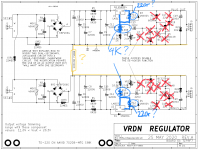
You're interested in the resistance from the ADJ pin to ground. In this case,
this means the group R7/R8/VR1 (for the LM317) and
R10/R9/VR2 (for the LM337) As Jim wrote, when these groups are at 4K,
you have about +/-24V. How you achieve that is up to you, but changing
R7 and R10 to 4K will give you a min voltage of about +/-24V.
If you use 2.5K for R7 and R10 you should be able to adjust from
about +/-15.5V to +/-25V
You still need to set the J3 and J4 jumpers.
Is it actually useful (and not only fun) to match the fqp3p20/fqp3n30? (Like, mo‘ good Sound?)
How can it hurt, other than economically? You test 50 parts, and pick out the four best-matched pairs. Then you discard (recycling preferred!) the other 42 parts. Assuredly your parts cost has increased by a factor of (50/8) = 6.25X. Test cost is zero because testing is enjoyable hobby-behavior; and hobby-behavior has zero cost, instead it has nonzero benefit.
But has the exercise done anything bad, electrically?
But has the exercise done anything bad, electrically?
How can it hurt, other than ...
discard (recycling preferred!) the other 42 parts.
nonzero benefit.
But has the exercise done anything bad, electrically?
🙂🙂🙂
As always, your response was ... remarkably ... inspiring...
So I take it that the quality-gain-factor is more or exactly zero, but not below.
Hmm... [emoji848]
Here's the story:
I had the occasion to melt a little bit of solder, so I started to source parts for the BA-3. (My next excuse not to start my F4 which scares me don't know why...)
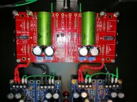
Stumbled on those PRP-resistors...
Hei, red resistors on a red PCB!
Checked the available values, which seem to be "strange" (there's a name for certain groups of values), some don't fit the BOM.
Piggybacking 2 resistors could be an option to come close.
But that's just stupid, I won't do it...
Finally, here's the question:
The BOM requires 10r, PRP has 11r... that's a 10% deviation. Would this work?
I second 6L6. Build the f4. My first ever soldering project and my favorite amp (vs many much more expensive commercial offerings).
Thanks, cal!
Yes, I will build the beast.
I just need to free up some mindspace (finish other projects on the deck) and then I’ll start. Maybe even before the ultraFSP[emoji6]
Yes, I will build the beast.
I just need to free up some mindspace (finish other projects on the deck) and then I’ll start. Maybe even before the ultraFSP[emoji6]
In my build the power supply consists off,
1 transformer,
x2 diode's/caps (one for each channel)
x2 diy store supper regs (one for each channel),
should the return to case be taken from the reg's board or the ba3 board.
also, will x2 bridge/thermistor be required at return to case.
1 transformer,
x2 diode's/caps (one for each channel)
x2 diy store supper regs (one for each channel),
should the return to case be taken from the reg's board or the ba3 board.
also, will x2 bridge/thermistor be required at return to case.
I have joined the ground of left and right power supplies together and installed x1 bridge/thermistor.
Still not sure where the ground should be taken from, BA3 board or Reg boards.
Can anyone help
Still not sure where the ground should be taken from, BA3 board or Reg boards.
Can anyone help
I have joined the ground of left and right power supplies together and installed x1 bridge/thermistor.
Still not sure where the ground should be taken from, BA3 board or Reg boards.
Can anyone help
Photos would help.
- Home
- Amplifiers
- Pass Labs
- The BA-3 as preamp build guide