don t agree with this...although buffering the vas output is benefical
in many ways, lateral mosfets from hitachi can be directly driven from
the vas output.
if the amp is carefully designed to take advantage
of this configuration, its benefits wont be limited to
its simplicity, there are more than that..
agree that it is not possible with hexfets , which require a heavier drive
current..
reagards,
wahab
It is true that the gate-drain capacitance in Laterals is smaller, but one cannot ignore the gate-source capacitance, even though it is bootstrapped in a source follower. This capacitance is also nonlinear. Transconductance of the laterals tends to be less than that of Verticals, so the effectiveness of the bootstrapping is smaller. This is especially an issue when driving low-Z loads. Saving a few pennies by eliminating a pair of BJT emitter followers doesn't seem to be a good tradeoff.
Cheers,
Bob
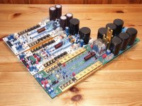
Pioneer idea of Mr. Hawksford and mainly Mr. Cordell's amp with practical results was for me something like a miracle. From that times I'm using this circuit with very well results and I must say, that it is good alternance to class A amps. Connections are hybrid of Borbely/Hawksford/Cordell and mine ( antisaturation circuit ), mosfets are vertical ones ( although I had try lateral too ), output power is from 100W up to 400W into four. Last version, type TYA III ( on the pic in the middle ), have really amazing sound, I heard never something better, believe or not...
Is nice " to stand on the shoulders of giants " - thank you, Bob, Happy New Year...
Pavel
Is nice " to stand on the shoulders of giants " - thank you, Bob, Happy New Year...
Pavel
Attachments
Last edited:
Pioneer idea of Mr. Hawksford and mainly Mr. Cordell's amp with practical results was for me something like a miracle. From that times I'm using this circuit with very well results and I must say, that it is good alternance to class A amps. Connections are hybrid of Borbely/Hawksford/Cordell and mine ( antisaturation circuit ), mosfets are vertical ones ( although I had try lateral too ), output power is from 100W up to 400W into four. Last version, type TYA III ( on the pic in the middle ), have really amazing sound, I heard never something better, believe or not...
Is nice " to stand on the shoulders of giants " - thank you, Bob, Happy New Year...
Pavel
Wow! Pavel you do REALLY nice work! And I'm glad to hear they sound so good.
Thanks for the kind words.
Cheers,
Bob
It is true that the gate-drain capacitance in Laterals is smaller, but one cannot ignore the gate-source capacitance, even though it is bootstrapped in a source follower. This capacitance is also nonlinear. Transconductance of the laterals tends to be less than that of Verticals, so the effectiveness of the bootstrapping is smaller. This is especially an issue when driving low-Z loads. Saving a few pennies by eliminating a pair of BJT emitter followers doesn't seem to be a good tradeoff.
Cheers,
Bob
as i said, there s more than the simplicity, which mean cost reduction..
if distorsion is the main concern, then buffering the vas at the output
and why not in his input, is the way to go..
though, the improvement gained is reduced by mandatory heavier
compensation that will partially ruin the extra OL gain...
with the vas as direct driver, we can get rid of the compensation capacitors,
that s exactly what i done, never mind the distorsion increasement..
BTW, what bandwith do you use when measuring distorsion?.
generally, i make wide band measurements up to 1 mhz..
although it s bizarre, i think measuring a 10 khz signal distorsion make no
sense if it s limited to a 22 khz range..
generaly, i use 220 khz as the bandwith for such high frequencies..
sure that the results are less pleasing...
regards,
wahab
Wahab,
Putting in a driver does not increase the amount of feedback compensation required because that wideband EF adds very little excess phase.
If you are relying on capacitive loading of the VAS by the output MOSFETs for compenastion, that is not a good thing. Those capacitances are nonlinear and somewhat variable. This also amounts to shunt compensation of the VAS, which is inferior to Miller compensation. The latter dumps gain at high frequencies while linearizing the VAS with the gain dumped through shunt feedback.
I measure THD with a measurement bandwidth that is always 10X the fundamental, using my distortion analyzer which does this automatically. So for 20 kHz THD, my measurement bandwidth is about 200 kHz. This captures all of the harmonics of interest while keeping a good SNR.
Cheers,
Bob
well, my project has been delayed by lack of employment ...:
and
Any Updates and PCB design for the original schematic.......!!!!!!!!!
well, it's been a long time. any thoughts, updates or even pcb layouts? at least for the front end? the bipolar output stage PCB (it's not an error correcting design) from ostripper's CFA vs VFA thread would probably mate very well with Bob's original front end or any of his updated versions: John's "do a balanced version" challenge result or Bob's book or the LSK489 app note.
mlloyd1
This discussion started in 2009 and in 2015 apparently there still wasn't anything available. I accidentally found this thread again cleaning up my bookmarks and wonder why I bookmarked it.
In 2021 I built the front end. Just for reference, here is my experience with the front end so far:
VFA front end - the Bunnyphant
In 2021 I built the front end. Just for reference, here is my experience with the front end so far:
VFA front end - the Bunnyphant
Last edited:
Everyone is waiting for someone else to lay out a PCB, build a prototype, test and measure it, then deliver boards or Gerbers. But nobody has done this yet.
Well, I'm working at it. 🙂
I designed my amplifier in a modular fashion and the complete amplifier at the moment uses a simple driver stage forming a kind of diamond configuration with a BJT output stage.
I plan to also build the error correcting driver stage and a MOSFET output stage. This would be close to Bob's amplifier. Prior to building the EC driver stage, I have a triple EF on the roadmap. So it might take some time to get to the EC.
My build varies a bit from Bob's design, but can be modified towards being closer to the original design.
I won't post any gerber files, but of course you can have boards.
- Home
- Amplifiers
- Solid State
- The Awesome Cordell Amp!