Rikard Nilsson said:Thanks Bob for popping in! 🙂
I also think it might be something like that. I have checked everything thorougly to rule out any silly connections I might have done, but ut looks ok. As soon as I get some spare time I will try removing my cascoded VAS and run the simpler version I know is very stable just to see if this helps the HEC. It could very well be a parasitic causing all this. (really hope so!)
By the way, how did you calculate the 270 ohm and 330 ohm resistors in your original schematics?
Rgs Rikard
Hi Rikard,
Can you post a schematic of your HEC design. Maybe something will pop out.
Cheers,
Bob
Certainly, thanks for asking! But please disregard the messy schematics as I haven´t finished the design. The EC is a pure "Cordell rip" and the rest is just my ideas. 🙂
By the way, Q23 and Q24 are FETs in the prototype, IRF620 and IRF9620, but I tried simulating BJTs instead and it seems ok. So I´ll replace the FETs in the prototype and see if it helps. I could also try increasing the gate resistors in the OPS just to see if any oscillation might stop.
🙂
By the way, Q23 and Q24 are FETs in the prototype, IRF620 and IRF9620, but I tried simulating BJTs instead and it seems ok. So I´ll replace the FETs in the prototype and see if it helps. I could also try increasing the gate resistors in the OPS just to see if any oscillation might stop.
🙂
Attachments
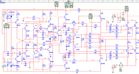
Figure 8 is absolutely amazing. So is your schematic, Rikard.
I'm going to have to take some painkillers so my brain doesn't hurt so bad while I try to comprehend these. Neat, I've never worked with MOSFETs. It seems they take a lot more knowledge and expertise to use well when compared to BJTs. 😱
I'll wait a while and get comfy with BJTs before I try a MOSFET output stage.
- keantoken
Well, the schematics isn´t really that fantastic, it looks much more complicated than it is. But once I´ve got things working properly I can always post a cleaned up schematic.
By the way, don´t hesitate using MOSFETs, they are really not that hard to work with most of the time. I found the 2SJ201/2SK1530 easier to work with as they are more temperature stable and probably not as prown to parasitics as the IRFP-types. it´s a pity they are harder to use in the EC circuit due to their low Vgs. Also, I really like the way they sound, but that´s more a question about circuit topology than the FETs themselves I think. Get rid of the odd overtones and your amp will sound better! 🙂
🙂
The HEX type fet can be more problematic wrt parasitics, not to mention not nearly as linear. But I find them to be a bit more robust and worth the effort to "correct" the non-linearity. Having no secondary breakdown helps them take the reactive current peaks and not melt. I've cranked out 100Wrms from 2 pair of TO-220 hexfets. Sure, the plastic case got a little warm (they were heatsinked to a 8" X 15" X 1/2" thick scrap piece of white brass.😀) but they still plugged along. Even if they would have all failed, I would be out about 4 bucks. How much do the 2SJ201/2SK1530 pair cost?🙄 When you look at the fact that the blown fuse costs more than the blown transistor
  , you can be a little less focused on protection circuits ect. In my last circuit, the source resistors are 100mOhm 1% TO-126 metal film resistors from Caddock. They cost about $3 each.
 The transistors are only 99 cents each.😎
The larger ones are a couple of dollars each.😎
Most of the time, the emitter/source resistors cost less than the outputs.

Sure, the plastic case got a little warm (they were heatsinked to a 8" X 15" X 1/2" thick scrap piece of white brass.😀) but they still plugged along. Even if they would have all failed, I would be out about 4 bucks. How much do the 2SJ201/2SK1530 pair cost?🙄 When you look at the fact that the blown fuse costs more than the blown transistor , you can be a little less focused on protection circuits ect. In my last circuit, the source resistors are 100mOhm 1% TO-126 metal film resistors from Caddock. They cost about $3 each. The transistors are only 99 cents each.😎 The larger ones are a couple of dollars each.😎
Most of the time, the emitter/source resistors cost less than the outputs.
syn08 said:Your conclusions are going to make a few people on this forum very happy. 😀
..........
Is that so?
Any idea who and why? 
I seem to have stability problem just as mentioned above! Question is, how do I best get rid of it. It seems to be outside the EC stage actually, so I figure I´ll have to try a few method with freq compensation. At the same time I don´t want to loose too much slew rate. Perhaps I shoud continue this in my other amp thread
http://www.diyaudio.com/forums/showthread.php?s=&threadid=127886&highlight=
I tried small caps from the VAS output to the base of the VAS inputs, and it sims ok but I loose quite a lot of speed.
http://www.diyaudio.com/forums/showthread.php?s=&threadid=127886&highlight=
I tried small caps from the VAS output to the base of the VAS inputs, and it sims ok but I loose quite a lot of speed.
Rikard Nilsson said:I seem to have stability problem just as mentioned above! Question is, how do I best get rid of it. It seems to be outside the EC stage actually, so I figure I´ll have to try a few method with freq compensation. At the same time I don´t want to loose too much slew rate. Perhaps I shoud continue this in my other amp thread
http://www.diyaudio.com/forums/showthread.php?s=&threadid=127886&highlight=
I tried small caps from the VAS output to the base of the VAS inputs, and it sims ok but I loose quite a lot of speed.
Hi Rikard,
With respect to stability of an EC amp design, I usually recommend two phases of investigation. First, make sure the basic amplifier has good stability with good margins without the EC in effect. The EC can be disabled by opening the resistor where one normally puts the EC error null pot in the circuit leading to the junction of the differencing amplifier emitter resistors.
Only after the underlying basic amplifier is well-behaved and characterized, enable the EC and look at stability again.
Cheers,
Bob
Thanks Bob! That´s quite interesting as it gives the oppurtunity to check exactly how the EC affects performance! 🙂
Yes, it does indeed make sense to use capacitance multipliers in the supply rails to the input
stage and VAS of a solid state amplifier, as long as the resulting voltage drop can be afforded.
When one uses boosted rails for the VAS and input stage, such a slight additional voltage drop
is definitely affordable. If we are talking about very high quality amplifiers, no one should be
complaining about the slight extra cost of boosted rails. Note that a capacitance multiplier
allows really good filtering of the input and VAS rails without dumping rail noise current into
a potentially sensitive ground through brute-force capacitance.
With regard to output stages, I have often thought that a MOSFET capacitance multiplier
("soft rail regulation") between the raw rectified rail and the supply for the output stage would
make sense. This capacitance multiplier would still feed into a fairly large capacitance local to
the output transistors themselves (perhaps 10-20,000 uF). This keeps raw ripple and RFI away
from the output stage. The price paid here is some power supply rail voltage loss ( a precious
commodity) and some power dissipation in the capacitance multiplier. The key advantage of
this as compared with a fully regulated supply to the output stage is that the voltage provided
by the capacitance multiplier tracks the available raw rail voltage, keeping regulator
dissipation down and retaining the advantage of dynamic headroom.
In any approach like this, one must always consider whether the output stage would have been
just better off with the greater headroom afforded by the same raw supply with the
conventional approach.
Cheers,
Bob
would that be a good idea here?
John Curl-
All Parasound power amps in my design range have cap multipliers in the driver stages.
myhrrhleine said:
would that be a good idea here?
Hi myhrrhleine,
John mis-spoke in his quote above. The JC-1 has a capacitance multiplier for the input and VAS circuits, but does NOT employ a capacitance multiplier for what we normally call the drivers.
In answer to your question, capacitance multipliers for the input, VAS and drivers for the Cordell design make sense because of the use of the boosted rails. I honestly don't know if capacitance multipliers would make sense for powering the output devices.
One interesting opportunity presents itself when a capacitance multiplier is used for the output devices. The capacitance multiplier pass transistors (here they would probably be MOSFETs) can be used to switch off power to the output stage very quickly under a fault condition.
Cheers,
Bob
Bob -- A question here. I like your idea here for using capacitance multiplier for "soft rail regulation" and protection for o/p stage. Would the charge stored in those 10,000 - 20,000 uF caps following the MOSFET be a concern as far as dumping energy into the speaker after the MOSFET is switched off?
Thanks....
Phil
Thanks....
Phil
PH104 said:Bob -- A question here. I like your idea here for using capacitance multiplier for "soft rail regulation" and protection for o/p stage. Would the charge stored in those 10,000 - 20,000 uF caps following the MOSFET be a concern as far as dumping energy into the speaker after the MOSFET is switched off?
Thanks....
Phil
This is what I am doing in my K800AB amp, now with 16 parallel pairs of ON Semi RETs in the OPS PSU. I'm dropping ~20V across the series pass transistors to allow 80A peak sinewave output at 20Hz without the series pass element dropping out. For this amp there is ~10,000uF after the series pass element.
10,000-20,000uF after the series pass element for a typical 50-100W class B amplifier would be overkill IMHO.
Use a high transconductance series pass element (parallel devices if necessary) to ensure low output impedance at LF instead.
Cheers,
Glen
PH104 said:Bob -- A question here. I like your idea here for using capacitance multiplier for "soft rail regulation" and protection for o/p stage. Would the charge stored in those 10,000 - 20,000 uF caps following the MOSFET be a concern as far as dumping energy into the speaker after the MOSFET is switched off?
Thanks....
Phil
Hi Phil,
Yes, that is a concern, and there is a tradeoff there. The time constant of 10,000 uF and 8 ohms is 80 ms, so that is an indication of what the loudspeaker would have to withstand.
We are, of course, free to use a smaller capacitance after the soft rail regulator, but then we tend to depend more on the ability of the pass transistor to handle very high current transients, and a bit more of those current transients will make their way back to the reservoir capacitors.
Cheers,
Bob
Thanks Bob. I've been gently kicking around some thoughts for o/p stage and speaker protection -- all the better if I can incorporate some regulation in there - so this gives more to chew on. But that will probably have to wait until I get some small upgrades made to my Cordell THD analyzer. 🙂
Phil
Phil
Bob Cordell said:
Hi myhrrhleine,
In answer to your question, capacitance multipliers for the input, VAS and drivers for the Cordell design make sense because of the use of the boosted rails. I honestly don't know if capacitance multipliers would make sense for powering the output devices.
Cheers,
Bob
how would a capacitance multiplier compare to a v-regulator?
same subject different topic
Hi
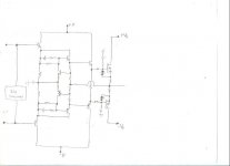
I have a question that may have been discussed in another watered down thread, but what would be the difference in taking the feedback to the EC emitter reference from the first pre-drivers instead of the last set of drivers? It seems to me you would want to compare the input of the circuit to the output of the circuit, instead just the gate drive to the output, and you would still have the positive feedback node. The only bad thing I see is you would be adding the phase shifts of the second pre-driver and driver to the feedback loop. Assuming these are very fast transistors, how much would the adverse affect on bandwidth be, IYO, and would it be worth it to include the errors of the drivers in with those of the outputs?
Just a thought...........or a mental movement.

Hi
I have a question that may have been discussed in another watered down thread, but what would be the difference in taking the feedback to the EC emitter reference from the first pre-drivers instead of the last set of drivers? It seems to me you would want to compare the input of the circuit to the output of the circuit, instead just the gate drive to the output, and you would still have the positive feedback node. The only bad thing I see is you would be adding the phase shifts of the second pre-driver and driver to the feedback loop. Assuming these are very fast transistors, how much would the adverse affect on bandwidth be, IYO, and would it be worth it to include the errors of the drivers in with those of the outputs?
Just a thought...........or a mental movement.
Attachments
Hi C.K,
Good point. This topic has been discussed a year or so ago. Regrettably, I couldn't find where and when exactly. But I do know that if the FB is taken from the emitters of the last drivers, you will get slightly less distortion.
Regards,
Edmond.
Good point. This topic has been discussed a year or so ago. Regrettably, I couldn't find where and when exactly. But I do know that if the FB is taken from the emitters of the last drivers, you will get slightly less distortion.
Regards,
Edmond.
Hmmm
I haven't actually performed an A-B test on measured distortion, but I can see a reduction in bandwidth being caused by the extra FB delay as a measure to increase distortion since it is bandwidth and not gain your looking for in this circuit, at least as it seems to me.🙂
Have you ever thought of using cascode, small signal mosfets for the last driver transistor? It seems to work well for me, but you have 2.25 Vgs(th) (x2=4.5V) added to the spread voltage instead of 1.3V. Trivial.🙄 The idea is that they are faster transistors to use as the (high freq) EC follower, and can still provide nearly an amp of current on demand. High ft small signal BJT's generally can't handle much current. In my test circuit, the TO-92 mosfet drivers are cascode with KSC2690/KSA1220. Is there a real advantage? I'm not really sure yet.
Chris
Bandwidth
Hi Chris,
I haven't actually performed an A-B test (in real life) either, only a quick sim.
It seems that you are worrying about the speed of the FB loop, right?
As Jan Didden has found out (see: http://www.diyaudio.com/forums/showthread.php?postid=1720508#post1720508) there exists an optimum when the BW of OPS proper and the BW of the FB/correction loop are equal. Since normally the BW of the OPS is the limiting factor (caused by gate resistors and gate capacitance), I don't think that the speed of the correction loop is a real issue. IOW, little is gained by using an ultra high speed driver.
Last but not least, I'm not an expert on HEC. As you probably know already, I rather prefer a GNF OPS.
Regards,
Edmond.
- Home
- Amplifiers
- Solid State
- The Awesome Cordell Amp!