Cheers for the feedback Mike, I've found another article on that heatsink I have in mind, with an 85W thermal load it's 29deg above ambient, using the standard fan. My use will have slightly less air throughput, but your article indicates 60W per channel, therefore 30W per FET, easy enough to stay under 25 aa.
Got my fan in the mail yesterday, it's a shame to have it out of view, looks so good, and can't hear it without sticking my ears into the blades, may need a re-wire though, it takes alot of heat to make it go fast.
Isn't it be best though to keep each channel in some kind of thermal contact also? I'll keep the airflow symmetrical enough, but maybe a copper bus bar linking them would keep them behaving more equal, lower distortion, and substantially increase the thermal reservior.
160VA and 300VA is all that's available locally, and there's a proportional price difference. In the future when money grows on trees I'll be able to replace them if they get hot.
160 VA should do the trick for a single channel.
You'll want to keep your output MOSFETs at the same temp. If your fan is temperature controlled, setting the bias may take a little extra time to get just right. Exercise patience and check your DC offset as things settle.
Speaking of transformers, Nelson wasn't kidding about rotating the transformers to reduce noise. I've noticed 20-30 uV differences by rotating them a few degrees. If you can measure noise levels that low, it's a great tweak: effective, sound, and free.
EUVL said:
Ah, what I'd give for a look at those.

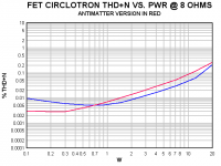
Somewhat preliminary, but here's a test of an "Antimatter" channel using the LSK389 boards.
The noise figure I measured in the audio band was impressive at about 15 uV, which probably accounts for the improved THD at tiny power levels.
Board file and info to be posted this week.
The noise figure I measured in the audio band was impressive at about 15 uV, which probably accounts for the improved THD at tiny power levels.
Board file and info to be posted this week.
Attachments
Mike, I can see an RCA close to the XLR in this new model....
Are you going to introduce an active Unbal to Bal adapter or add an input transformer?
Are you going to introduce an active Unbal to Bal adapter or add an input transformer?
I really recommend balanced operation. The two-stage capacitor-less iteration is certainly the way to go in my mind.
However, realizing that might not be possible for some constructors, I had intended to look at three circuits (2 active, 1 transformer) for "unbalancing" the input.
None have been tested, and it will probably be quite some time before I get to them all.
In the meantime, perhaps a few solutions could be worked out here in the forum.😉
Looks like a good alternative. I found me a local source for the discontinued 2SJ74 though, stocked up with enough to make a few pairs.
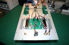
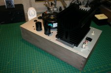
Got the rest of my parts from digikey today, now I've got all the components. Tomorrow I'll cut some parts for the chassis, hoping to have it on the way to the anodiser on Sunday.
I'll make a picturey worklog on the AudioEnz forums, and put a link here to it.
Are you going to get Antimatter Circlotron badges made?
Pikefish said:Are you going to get Antimatter Circlotron badges made?
I hadn't thought about it, but it might be cool to make some black-on-silver rather than silver-on-black.
I am seriously considering some Pass-like bias meters for my personal pair though.😎
I was thinking a Russian block capitals type font would be a good theme, crazy soviet space technology etc. I'm going to carve myself a big mold into wood and cast it in lead.
As for the 2SJ74, I'll not assist in them leaving the country until the rest of the world runs out, but gladly share the link with locals (and have). Just found it with a bit of googling anyway.
As for the 2SJ74, I'll not assist in them leaving the country until the rest of the world runs out, but gladly share the link with locals (and have). Just found it with a bit of googling anyway.
2SJ74
There are still tens of thousands of them around.
Just look at the Market place here at DIY Audio.
Patrick
There are still tens of thousands of them around.
Just look at the Market place here at DIY Audio.
Patrick
Hi everyone,
I Have looking for 2SJ74 in many places locally no one seem have even just 4 pcs that I need so I have 2 choices :
1. Use bipolar instead of 2sj74
2. Use N channel FET
Any input ???????
Dont ask me to buy from overseas its scarrrrrrrrrrrrrrrrry
I Have looking for 2SJ74 in many places locally no one seem have even just 4 pcs that I need so I have 2 choices :
1. Use bipolar instead of 2sj74
2. Use N channel FET
Any input ???????
Dont ask me to buy from overseas its scarrrrrrrrrrrrrrrrry
http://www.diyaudio.com/forums/showthread.php?postid=1609013#post1609013
He is not too far from you, I think.
Patrick
He is not too far from you, I think.
Patrick
- Home
- Amplifiers
- Pass Labs
- The Amazing Fet Circlotron by Mike Rothacher