I have SSHV2 ready for HV, bench psu 0-30V/3A adjustable & other fixed 5V/1A, can I drop to 2.1V with 4R7 5W?
Last edited:
You got 2) wrong.
Now is OK?
Attachments

Sure, but I insist that when you get help, you make an effort and do things as detailed as possible. Your picture did not include the resistor, or the power supplies properly labeled. You make it difficult for us to give you help. When someone helping you puts more effort into making a picture that only helps you, you should be worried! 🙂
Next time I will try to do more accurate, thanks again.
Iko I guess 25VDC is positive like 100V & 2.1V, right? I only want to be sure.
Iko I guess 25VDC is positive like 100V & 2.1V, right? I only want to be sure.
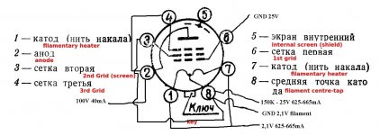
I don't know what you mean, the drawing should be clear. A variable supply that you set to provide 25 volts DC. You put the negative lead to the 150k resistor and the positive lead to ground. That will under bias the tube, but then you adjust this towards 15V or so.
OK I will do like exactly like your schematic.
The 4P1L seller marked both tubes with number 73?
The 4P1L seller marked both tubes with number 73?
Yes, do the wiring exactly as in the drawing. Pay attention to what is + and what is - on the drawing.
Hard to tell what the seller means by the number 73.
Hard to tell what the seller means by the number 73.
Thanks Iko for your patient. Iko plate voltage 100 or 200VDC? I ask because minimum Vout with tx on hand is 125VDC with 15K dummy load? You wrote 100VDC but schematic said 200VDC?
You start with 100V, to be safe. Then increase slowly while monitoring the current, until you get to 200V, which is the target that you want the tube tested at. If you got to 200V on the plate, while you have -25V on the grid, and you measure, maybe 10mA current through the tube, you can then start adjusting the voltage on the grid, slowly, watching the current going up. When you get to the desired current, which maybe it is 20mA or so, then you write down what voltage you have on the grid. Could be -14V or could be -16V.
But if you don't have a variable high voltage supply perhaps you can start directly with +200V on the plate, and only adjust the grid voltage from -25 towards -15 while monitoring the current.
But if you don't have a variable high voltage supply perhaps you can start directly with +200V on the plate, and only adjust the grid voltage from -25 towards -15 while monitoring the current.
To monitor the current I do like the #26 tube: putting 100R between B+ & tube plate?
Last edited:
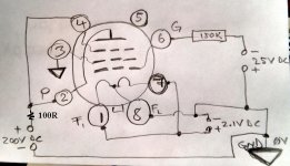
To monitor the current I do like the #26 tube: putting 100R between B+ & tube plate?
Yes, and you measure the voltage across that 100R resistor. The current will be the measured voltage divided by 100.
Yes, I know I did the same in the #26 preamp🙂
Voltage drop 100R max. 0,583V with 0-25VDC set to 0V set to 66,5VDC = 0V across 100R
Voltage drop 100R max. 0,583V with 0-25VDC set to 0V set to 66,5VDC = 0V across 100R
First of all sorry for my bad English, I will try again:
I have measured the voltage across the resistance of 100 ohms with the voltages of the schematic and it measures 0V, I lowered gradually from -25V up to -0V monitoring the current and up to -6,65V the voltage across the resistance measures 0V, the maximum voltage across the resistance is 0,583V when there is applied -0V on the grid.
I have measured the voltage across the resistance of 100 ohms with the voltages of the schematic and it measures 0V, I lowered gradually from -25V up to -0V monitoring the current and up to -6,65V the voltage across the resistance measures 0V, the maximum voltage across the resistance is 0,583V when there is applied -0V on the grid.
There are only two possibilities here: 1) bad tube, and 2) you made a mistake in setting up the test.
I tested the two tubes that I have on hand, I will check again the set up test.
GND is chassis OK?
GND is chassis OK?
- Home
- Amplifiers
- Tubes / Valves
- The all DHT SET Headphone Amp