The good side effect of this is that the price of 307a has dropped significantly. 😀
+1😀
YHPMThe Tribute I ordered one is of nano-tech non-amorphous core (finemet), its fairly experimental for this application although has been done with the Japanese Feastex Takatsuki 300B commercial amp. <snip>
The JJ 2A3-40 does not inspire confidence, for working above the usual 2A3 voltages.
compare the published curves:
http://www.jj-electronic.com/pdf/2A3.pdf
And, to keep the comparison fair - intramural, even - please see their 300B:
http://www.jj-electronic.com/pdf/300 B.pdf
And see how the 2A3's behaviour goes bad, much above 400V.
The 40W thermal rating is deceptive. It's the internal geometry that makes the 300B the beauty it is (when well fed, and watered).
.
That or the curves are marketing mumbo jumbo.

It'll work just fine.
Since for headphones, output power is not paramount, I'd sugguest going parafeed. Put a gyrator on top of the output tube, and use a 10k primary OT. Much, much better linearity - with headphones you can really hear small differences in sound quality.
I would also sugguest going fixed bias, since you have a coupling cap anyway.
Thanks, in place of a gyrator I have in mind to use Salas shunt reg SSHV2, sorry my ignorance how can go fixed bias?
It'll work just fine.
Since for headphones, output power is not paramount, I'd sugguest going parafeed. Put a gyrator on top of the output tube, and use a 10k primary OT. Much, much better linearity - with headphones you can really hear small differences in sound quality.
I would also sugguest going fixed bias, since you have a coupling cap anyway.
This is absolutely right for most headphones. It is the right approach unless you have headphones (like the new planars) that require 1W+. Sowter makes a perfect parafeed OPT for this.
It'll work just fine.
Since for headphones, output power is not paramount, I'd sugguest going parafeed. Put a gyrator on top of the output tube, and use a 10k primary OT. Much, much better linearity - with headphones you can really hear small differences in sound quality.
I would also sugguest going fixed bias, since you have a coupling cap anyway.
Fixed bias for the output tube?
Fixed bias for the output tube?
For low power parafeed my experience is to just build a spud amp with a high gm high mu IDHT. You only need to move to two stage with planars.
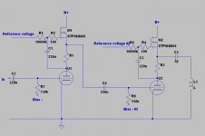
merlin el mago, this schematic demonstrates what I meant.
L1 is OT primary.
Fixed bias instead of RC, gyrator plate loads on all stages, parafeed output.
Quality of C5 is very important, so go Russian NOS. Best quality for little bucks. Go as small as you can get away with, 2µF is ok for 10k primary.
B+ should be regulated as you were planning to do.
L1 is OT primary.
Fixed bias instead of RC, gyrator plate loads on all stages, parafeed output.
Quality of C5 is very important, so go Russian NOS. Best quality for little bucks. Go as small as you can get away with, 2µF is ok for 10k primary.
B+ should be regulated as you were planning to do.
Attachments
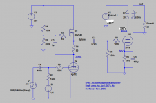
Just take the bias supply out of the schematic, and connect the 150k resistor to ground. So 150k between grid and ground, instead of grid and bias -.
By the way, for headphones, I would sugguest 4P1L driving 4P1L. It has all the drive and volume you'll need for regular headphones, and really good sonics. Cheaper filament supplies!
This kind of amp can drive both headphones and speakers, so it's really versatile and useful.
By the way, for headphones, I would sugguest 4P1L driving 4P1L. It has all the drive and volume you'll need for regular headphones, and really good sonics. Cheaper filament supplies!
This kind of amp can drive both headphones and speakers, so it's really versatile and useful.
hi Felipe,
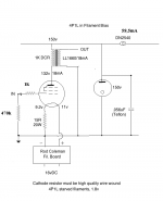
The filament bias voltage, and the circuit are OK. They can be used with no changes - provided you use the same anode-voltage (about 132V).
The filament bias circuit needs no cathode bypass cap, so the sound should be good.
You can use a CCS load, or the "gyrator load" in IKO's drawing, to get higher gain.
Please make the Gyrator's current-set resistor (R1 in the gyrator schematic) adjustable, so that you can get the 18mA shown in the filament bias drawing.
If you want a different anode current, please check the 4P1L curves, and set the filament bias resistor to give the right bias.
Iko's 4P1L fixed bias can't be modified to your filament bias? do you suggest is better fixed bias for Iko's schematic?
Do you refer to R1 MrCurwen's schematic and R6 Iko's schematic, right?
Do you refer to R1 MrCurwen's schematic and R6 Iko's schematic, right?
I think Mr. Coleman means that you need a certain amount of current for filament bias to be on point. With another amount of current thru the tube you need to adjust the filament bias resistor value.
Please correct me if I'm mistaken!
However, with the plate gyrator, you cannot adjust the current going thru the gyrator and subsequently, the tube, but only the plate DC voltage. That is adjusted via the voltage reference in my schematic. With a certain plate DC voltage, the tube will draw a certain current, so it's adjustable that way.
A plate CCS is of course adjustable via current sensing resistors.
Yes, that's what I mean!
It is a lot of work to change the filament bias network (multiple high power resistors, plus the change to the regulators sometimes) so it is better to make the anode load current adjustable.
So first, decide on the current, and set up the filament bias. Then adjust the anode load till the whole is in balance.
This kind of amp can drive both headphones and speakers, so it's really versatile and useful.
Could you post schematic?
Just take the bias supply out of the schematic, and connect the 150k resistor to ground. So 150k between grid and ground, instead of grid and bias -.
By the way, for headphones, I would sugguest 4P1L driving 4P1L. It has all the drive and volume you'll need for regular headphones, and really good sonics. Cheaper filament supplies!
This kind of amp can drive both headphones and speakers, so it's really versatile and useful.
For sensitive headphones (need ~ 5-10 mw), would the microphonics be low enough?
Hi Felipe,
35 mA sounds quite right. And you need about 240V Uak. There is slight difference between tubes. You are looking good with +300V before the CCS.
Instead of having fixed bias and add the capacitor to separate the input, I would use quasifixed bias through filament bias. You will lose a little amplification, but get rid of Cin and Ck. The only disadvantage is that you will need a raw supply at about 27-28V and 685mA(650+35) and Rod's regulator.
Best,
Radu
- Home
- Amplifiers
- Tubes / Valves
- The all DHT SET Headphone Amp