Go to:
http://www.fairchildsemi.com/products/discrete/
For samples, click the Request Samples link off the main page for descrete devices:
I requested 12 each of 3 products and it worked. My friend tried requesting 50 each of 2 products a few days ago, and it didn't work. I would just keep it to 12 each of 3 products.
They should send you a confirmation e-mail, then you will get a status e-mail when it ships. It took them 4 days to get them to me.
You do have to register for an account to get samples, but it was just a simple form with an instant reply.
I just put in another sample request for these:
PART Number QTY
#-----------------------------------------------------------------#
ISL9K18120G3 12
ISL9K30120G3 12
ISL9R30120G2 12
#-----------------------------------------------------------------#
--
Brian
WAY OT: Microchips
Hi Brian,
Microchips are great. Here is my latest project. On a 1.8"x1.6" board, I have a servo controller (PID encoder and 2.5A amp), and a microstepping stepper controller with 2.5A amp. Board communicates over CAN.
PIC18F458
Easy to design and program...
Dale
Hi Brian,
Microchips are great. Here is my latest project. On a 1.8"x1.6" board, I have a servo controller (PID encoder and 2.5A amp), and a microstepping stepper controller with 2.5A amp. Board communicates over CAN.
PIC18F458
Easy to design and program...
Dale
Attachments
I am using a PIC18F452. It is packed with features. A professor at my school made a board and a serial interface that allows you to easily program it over serial and run debugging software on it. It is pretty cheap. Here is a picture of my board driving my vfd.
My roommate has taken the class and is helping me with the remote controlled pga2310 volume control. I will make it 6 channels for use for movies, and stick with the BOSOZ for my aleph 2s when I finish it finally.
For more information on the PIC and software, go to:
http://www.picbook.com/
It is a good reference book to get you started and comes with the pcb to build the board. The rest of the board is available from digikey as a package: 18F452-KIT-ND
--
Brian
Attachments
There is one thing I don´t see at all.
Proper function of AX assumes identical electric properties of borth sides of the amp, i.e. identic active parts ( input ones first of all).Not every body is able to choose them as Mr. Pass can ( and does). Using one current source for two input transistors we are not able to set them equal current. I think. Why dont you use separate curr. source for each input MOSFET?
Proper function of AX assumes identical electric properties of borth sides of the amp, i.e. identic active parts ( input ones first of all).Not every body is able to choose them as Mr. Pass can ( and does). Using one current source for two input transistors we are not able to set them equal current. I think. Why dont you use separate curr. source for each input MOSFET?
Actually, this defeats the purpose of the differential pair. The operation of the circuit depends on a fixed current being shared by the two transistors, such that any current drawn by one side is taken away from the other side. Notice that the current is split and flows into R23 and R25, forming the drive voltages for Q2 and Q11. Even without matched transistors, the input pair will work ok.
Actually, this defeats the purpose of the differential pair.
The sources of the input pair must be coupled together to act as a differential pair. Only when using source degeneration, it is possible to use two current sources. Using one current source and triming the relative values of source resistors for each side, is more often used for this current balance. For an example of a two current sources feeding a diff pair see the link. They are used to keep DC currents out of the adjustable source degeneration resistors. (for several reasons)
http://www.passlabs.com/pdf/aleph/apserv17.pdf
Koy states:
"Proper function of AX assumes identical electric properties of borth sides of the amp, i.e. identic active parts ( input ones first of all)."
Identical is perhaps a little hard a design goal, but good matching for both sides of the circuit will provide better performance and good matching of the input pair is absolutely required for low DC offset.
A very good question,
Fred
As I know about - it is done by adding resistors to the source to lower variations of transconductances as smaller as possible - to equalize them. Unfortunatelly it is not very efficient with MOSFETS
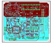
Well, I have finished my pcb layout and am sending the design out tommorrow after I look over it one more time.
pcb layout pictures
Am I correct in assuming that with the X front end, this is essentially a pair of bridged aleph amplifier, thus each side sees half the load impedence. This would mean that the output stage would have to be capable of driving a 2 ohm load (ignoring dips in the impedence curve for now). This would mean that since this is basically a bridged version of the mini-a, which was 10W, so his Aleph-X is around 37W into 8 ohms, accounting for the resistor loses from the ones tied to ground. Does this translate to around 74W into 4 ohms? Will the design be stable into 4 ohm speakers if I double the number of output devices and effectively doubling the current?
My current plan is to stick with the +/- 15v rails and doubling the amount of current for the output devices. Am I fine keeping all of the same resistor values of the original schematic and just running two sets in parallel? Are there any values that I need to change to make this work, besides a larger transformer? (I am planning on using my Aleph2 transformer with a variac for now.
pics of the chassis I am intending to use:
chassis pic 1
chassis pic 2
I have two of these, which should be capable of dissipating 300W each at least. If I double the current of Grey's circuit, which he stated draws 4.5A, then does this mean that this will draw 9A? Does this directly correlate to 9A x 15v x 2=270W of power dissipation?
--
Brian
Yes brian 4.5x2 still equals to 9. 😉 But 9 should be x 30 =270watts
270/8~34 w per mosfet.
EDIT: You just corrected yourself didn't you?
270/8~34 w per mosfet.
EDIT: You just corrected yourself didn't you?
grataku said:Yes brian 4.5x2 still equals to 9. 😉 But 9 should be x 30 =270watts
270/8~34 w per mosfet.
EDIT: You just corrected yourself didn't you?
I did a sanity check on it after I posted it and realized that I forgot the factor of two. Thanks for the response.
So, 270W dissipation is the magic number, and my girlfriend says that the chassis should dissipate 300W pretty easily. I guess I will be running monoblocks.
--
Brian
No. 🙁
If you stick to +/-15 V with a 9 amps bias,
then you will dissipate (15-0.5) X 2 X 9 means
261 Watts.Because your PSU is symmetric and
the Aleph X draws like conventionnal Alephs
same current on both sides of the PSU. 😉 So a little more
than output calories...
I planned to go for a +/- 22 V supply at a 4.25A bias.Basically two Aleph 3 bridged.
In my case the heat dissipation is (22-0.5) X 2 X 4.25 means
182.75 Watts.And a little more draw from the PSU
My PSU is OK to give me towards 12.5 Amps bias.Adding more output devices parallel permits more current for the speakers
And last but not least;big capacitors suitable for this purpose,and good heatsinking!!! 🙂
My voltage gain will be lower than Greys original.I plannned 20 dB ( x 10) balanced ,as with ZLS or even better XZLS I have enough gain for the horns
😉
Best regards
Anael
wouldn´t be a good ide to place the caps across the +/- and not to +/0/- to get them to hold more energy??
/micke
/micke
One last question, I noticed that each device would be dissipating 33.75W. Is the in the SOA (safe operating area) of the IRFP240? I could add another pair on each side, and make it 12 devices instead, decreasing this to 22.5W per device (with same total current).
By my calculations, this would mean using 0.33R resistors, right?
calculations:
9A / 12 devices = 0.75A each device
(.5A)^2 / 0.75A = 0.33R
--
Brian
By my calculations, this would mean using 0.33R resistors, right?
calculations:
9A / 12 devices = 0.75A each device
(.5A)^2 / 0.75A = 0.33R
--
Brian
nar said:No. 🙁
If you stick to +/-15 V with a 9 amps bias,
then you will dissipate (15-0.5) X 2 X 9 means
261 Watts.Because your PSU is symmetric and
the Aleph X draws like conventionnal Alephs
same current on both sides of the PSU. 😉 So a little more
than output calories...
I planned to go for a +/- 22 V supply at a 4.25A bias.Basically two Aleph 3 bridged.
I would like to run higher voltages, but I am concerned that I won't be able to get enough current to the output devices if I do this.
How do I calculate how much bias is really needed to drive 4 ohm speakers. The impedence doesn't drop below 3.2 ohms.
--
Brian
Some calculations are here: http://www.diyaudio.com/forums/showthread.php?s=&threadid=3748&perpage=15&pagenumber=8
Read further because Grey made mistake initially but corrected later.
Read further because Grey made mistake initially but corrected later.
Wow,
Brian,
If you're correct, then doubling or tripling the output transistors/power resistors and increasing the current would certainly take the guess work out of recalculating the resistor values in the front end. I really hope you're correct.
John Inlow
Brian,
If you're correct, then doubling or tripling the output transistors/power resistors and increasing the current would certainly take the guess work out of recalculating the resistor values in the front end. I really hope you're correct.
John Inlow
John,
The only reason that I am not recalculating resistor values is that I think that the current power the it puts out is enough, but I am concerned about the ability to run my 4 ohm speakers. If they go as low as 3.2 ohms, then this is the same thing as a normal Aleph running a 1.6 ohm load, which without modifications would be current limited.
Right now, I am running some calculations and considering upping the voltage a little bit and increase the current to make a little higher powered version with about 300W total dissipation.
Here is the post from Grey, quite a while back, and I made the correction that he noted later:
Peter, thanks for reminding me of this. I couldn't find it in all of the posts of the thread.
--
Brian
The only reason that I am not recalculating resistor values is that I think that the current power the it puts out is enough, but I am concerned about the ability to run my 4 ohm speakers. If they go as low as 3.2 ohms, then this is the same thing as a normal Aleph running a 1.6 ohm load, which without modifications would be current limited.
Right now, I am running some calculations and considering upping the voltage a little bit and increase the current to make a little higher powered version with about 300W total dissipation.
Here is the post from Grey, quite a while back, and I made the correction that he noted later:
Grey once wrote:
Okay, hold on to your hat. This is Uncle Bear's rule-of-thumb recipe for building an Aleph:
Step One--
Choose a target RMS wattage into your speaker. Remember that most speakers have peaks and troughs in their impedance curve, depending on frequency. Plan accordingly. Leave a little elbow room.
Step Two--
Determine what that wattage/speaker impedance works out to be in terms of voltage and current.
Step Three/a--
If you're building a normal Aleph like the original product line, multiply the voltage from Step Two by 1.6. This is your DC rail voltage. Put a + and - in front of it, and you're in business.
Step Three/b--
If you're building a bridged Aleph like the XA200, multiply the voltage from Step Two by .8.
Step Four/a--
If you're building a normal Aleph, divide your current from Step Two by two. This is your total bias current.
Step Four/b--
If you're building a bridged Aleph, the current from Step Two is your total bias current for both sides of the amp.
That will get you in the neighborhood. Everything else boils down to keeping the power dissipation down to reasonable levels on the output devices, and adjusting the resistors accordingly.
Peter, thanks for reminding me of this. I couldn't find it in all of the posts of the thread.
--
Brian
- Home
- Amplifiers
- Pass Labs
- The Aleph-X