If everything goes well, I should have my X running end of this week. I just had some other projects running (in terms of income) so that's why delay. There is another schematic on page 23, posted by rtirion, who probably also has a working version of the amp.
I started front end board yesterday and I'm done half way. I much more prefer 3 dimentional circuits than PCBs, there is so much more possibilities as to mounting the parts.😉
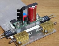
You see power resistors up front (series output and to ground) and differencial pair in a back. The suspended circuit is the CCS based on Fred's circuit. Please note a cute heat sink on ZVP mosfet.😉
I started front end board yesterday and I'm done half way. I much more prefer 3 dimentional circuits than PCBs, there is so much more possibilities as to mounting the parts.😉
You see power resistors up front (series output and to ground) and differencial pair in a back. The suspended circuit is the CCS based on Fred's circuit. Please note a cute heat sink on ZVP mosfet.😉
Attachments
The input caps look to be the usual 1-to-2 uF 250 polyporpylene from panasonic,
I put them in my PCB design, although I am planning to drive my AX with the BLS which has already two output caps and I will most likely leave them out.
Carpenter, I understand that you want to get the ball rolling on this Aleph X pcb but, although it has taking him 10 posts to make the point and 10 more to re-state it and he is probably not going to be part of the purchase, Fred has a very valid point. It is better to iron out all the issues now and delay the production by a couple of weeks than have a problem later. If the board is working now it will be working later with the small mods people are suggesting.
Peter
that's simply magnificent!
Peter,
Nice work! I will look over the other schematic. As for the power supply, how much voltage are you giving your Aleph-X? What is your expected power? I am planning on just using my Aleph 2 transformer, and borrow a variac from school for now for my power supply.
--
Brian
Nice work! I will look over the other schematic. As for the power supply, how much voltage are you giving your Aleph-X? What is your expected power? I am planning on just using my Aleph 2 transformer, and borrow a variac from school for now for my power supply.
--
Brian
BrianGT said:Peter,
Nice work! I will look over the other schematic. As for the power supply, how much voltage are you giving your Aleph-X? What is your expected power? I am planning on just using my Aleph 2 transformer, and borrow a variac from school for now for my power supply.
--
Brian
I'm using +/- 20V DC supply. It is the same transformer as A75, just primaries connected in series for half of the secondaries. Too bad this can't be done with those nice Victoria Magnetics toroids (one primary winding only). I expect to get 100W of power from my X. Don't ask me in what load, because I don't really care. My power is dependant on the chassis I'm using and I plan to run the amp at around 50 deg C.
CCS is described here: http://diyaudio.com/forums/showthread.php?s=&threadid=5980&perpage=15&pagenumber=6 I don't even know if it will sound better than the original from Nelson, but why not give it a try. Maybe Harry's suggestions will be put to use finally?
 😉
😉 As to Carpenter's board, I think it's pretty full proof design and I don't really expect any problems. It's not the best example of finesse in board design, but nothing wrong either. If he wants to push the production as fast as possible, why not give him support.

I see we broke 100K when I wasn't looking.
😎
I speculate that Fred's avatar is a picture of Julian Schwinger.
The relay you see on the Aleph X is the external turn on
switch, driven by 12 volts applied to terminals on the rear
panel. It is in parallel with the front panel switch.
There is another big relay underneath on the left side of the
board in the picture, which would be a speaker relay, but
we have ended up not using it in production.
Aleph X question
True if I go for a 8 amps total bias the maximum output current to the speaker will be 8 amps ??? And not 16 amps?
Is a 1000VA 2X 20 V suitable for it , in fact I have 2 500VA 2X20V on hand,and with 2 bridges I should have a 25 amps capability...
Nelson...are you here?
True if I go for a 8 amps total bias the maximum output current to the speaker will be 8 amps ??? And not 16 amps?
Is a 1000VA 2X 20 V suitable for it , in fact I have 2 500VA 2X20V on hand,and with 2 bridges I should have a 25 amps capability...
Nelson...are you here?

I knew it was a Physicist....I just didn't know who...couldn't even get a clue from the blackboard because I couldn't read it. I haven't seen a picture of Rabi that young. Are you sure Schwinger wouldn't be more appropriate?
1/137
1/137
My favorite quote from Isador Rabi:
"A man's virtues should never be used against him."
This was in reference to Feynman's reluctance to receive
an award given by the same man as booted Oppenheimer.
"A man's virtues should never be used against him."
This was in reference to Feynman's reluctance to receive
an award given by the same man as booted Oppenheimer.
Re: Aleph X question
True. But the supply voltage is 1/2 the output swing because
it's balanced, and thus the efficiency is the same.
nar said:True if I go for a 8 amps total bias the maximum output current to the speaker will be 8 amps ??? And not 16 amps?
True. But the supply voltage is 1/2 the output swing because
it's balanced, and thus the efficiency is the same.
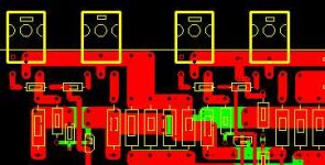
Here is a snippet of my pcb.
Since I am planning to drive an MTM with impedance dips ~3 ohms the amp will be biased at 6 amps total and powered at +/-15V with 2 devices in parellel (total of 8 irfp044/chn).
The PCB is doubled up with metallized through holes to add cross section to the traces. The picture shows the power section of the left end side of Grey's schematic, basically the dual Q1 and Q2's.
The schematic is Grey's standard with the two resistors from the output -back to the S's of the differential. CS is the standard of Grey. At this stage of the game I see no need for a ultra high rejection CS.
Attachments
CS is the standard of Grey.... I see no need
The zener and 1.5 K bias resistor will attenuate the supply ripple seen across the reference voltage(the zener) by a ratio of about 50 to 100. Since one can expect fairly large amount of ripple for an amp biased this hard, I feel this is not a very clean voltage reference for the current source and would not be suprised to see up to 5mV of supply related noise across the voltage reference. Not very quiet and a very good canidate for sonic improvement in my and others experience.
This amount of noise is well above the level of zener noise that has prompted many designers to use a low noise integrated circuit voltage references, such as the LM329, for an improvement over a zener. Don't take my word for it, but realize that many audio designers have be using the LM329 and even better references for over ten years in good audio designs. The subject of low noise references has been discussed in the forum. I guess this is more 'late of the art" than "state of the art". It is the first thing I would change in the design. I guess it is not an absolute necessity, but I would think using a larger resistor to the positive supply to get more noise rejection. This would be the an easy improvement with no increase in complexity over the Grey implementation at any rate. I believe you want at least 5mA through the zener.
http://www.diyaudio.com/forums/showthread.php?s=&threadid=1437&highlight=LM329
http://www.diyaudio.com/forums/showthread.php?s=&threadid=4879&highlight=LM329
Fred
Hi, John InlowWould you care to elaborate? The statements read well, but, what do they mean to you?
Please do not have any hard feeling.
With my deep interest, I have thought about Aleph-X as going well technically. But, I am lately confused after reading some posts. Therefore, that monologue is actually my complaint as the confusion has made me saddened. I hope you will get to a successful production.
JH
hard feelings?
Hi JH
You're projecting a bit of your feelings into my response. I thought the quote you offered was a nice read. But, I came away not understanding how you felt about the quote. My feelings are not hurt in any way.
This is an interesting exercise, dealing with the various personalities in this group. I'm usually a bit of a loner and belonging to a group is forcing me to stretch my comfort zone.
John Inlow
pcb artwork problem......
Hello all,
I'm hitting a snag with regards to the current artwork. It's written on a Mac with Photoshop and guess what? You got it, wrong format. It's looking more and more as if I'm going to have to redraw the art using the "proper" language.
Does anyone have a shortcut? Let's brainstorm.
If a redraw is the only way out, then we can adopt some of the extra circuit mods while we're at it.
Peter, Fred, anyone; do you have any ideas, in the spirit of Zen, that are simple to implement?
John Inlow

John, I can draw the pcb up for you in Protel, and export gerbers for you if you want. It shouldn't be too difficult since you already have the layout done.
--
Brian
--
Brian
I have been revising with my layout
Except input DC blocking caps, all the parts are now on the PCB
Q5, Q6 and Q7 can now be mounted on a common heatsink.
Is this advisable?
Yea:ˆ
Nea:ˆ
Their are now 3 jumpers 🙁
All resistor (except R27) pads are now spaced 12mm.
Added some local PSU electrolytics sized to take <FONT FACE="Symbol">»</FONT> 220u/25V cerafine/muse/blackgate etc
2 Gnd pads ?
I decided to mount the power MOSFETs in such away that Q2 and Q10 are inverted, I intend to use a channel or a dual flanged heatsink as available from Conrad Engineering, this helped keep the layout symmetrical.
The board size has increased a bit , its now 115mm x 74mm
<hr width="95%" align=center>
<center><font size="+2" face="Fantasy">WARNING
---THIS BOARD IS UNTESTED---</font></center>
<hr width="95%" align=center>
Any suggestions?
Regards
James
Attachments
- Home
- Amplifiers
- Pass Labs
- The Aleph-X