Some notes
I definitely agree with Fred on regarding the voltage reference. No reason to go through all this trouble and *not* use an LM329. I have a few dozen LM329AH, and I used one in my A-X prototype. Works fine, no reason to not use it. The AH metal can part is discontinued, but the plastic packages are still available.
The input differential pair should certainly be mounted on the same sink, or should use a dual FET for maximum tracking. I believe Fred listed some dual FETs earlier, or you can grep Digi-Key.
Input coupling capacitors seem unneccesary. Making provisions on the board for the cap is fine I guess, but if I was building one I would just jumper it.
Oh, and I also agree with Peter that this circuit is so simple, it deserves to be built point-to-point.
Any suggestions?
Thermal coupling of the diff pair and a schematic to compare against the layout?
Thanks,
Fred
Thermal coupling of the diff pair and a schematic to compare against the layout?
Thanks,
Fred
tvi said:Any suggestions?
[/B]
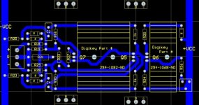
Not sure if I like the idea of the multiple +VCC and -VCC inputs.
Now I am interested in making my own layout... I will what I can do with it tonight.
--
Brian
Current source mosfet runs a bit warmer than differencial pair, but it won't hurt much and simplifies construction. The spacing of differencial pair shoud provide enough clearance for the screw (I dont see enough space for a nut, but you can always tap the hole🙂).
I like this layout, very compact. Separate voltage feeds can be used to the advantage, with separate capacitor banks.
What type of 3W resistors you had in mind when designing board, Caddocks?
I like this layout, very compact. Separate voltage feeds can be used to the advantage, with separate capacitor banks.
What type of 3W resistors you had in mind when designing board, Caddocks?

tvi:
You don't need any thermal coupling of the CCS to the diff pair. Instead, I would rotate the diff pair transistors 90 degrees each so you can mount them back to back and get much better thermal coupling between them... This is far more important, in order to minimize DC offset and DC drift. Best is if the diff pair 9610s can mount directly to each other (with an insulating pad between!), and a pair of identical heatsinks mounted to the outside faces of the diff pair. That is how I would do it, as it gives the tightest thermal coupling possible...
High current traces for the power transistors look like they should be beefier. Depending on the supply voltage used, some of these traces will be carrying very heavy currents! Make 'em as thick as you can fit on the board. Also, it would be nice if the main power transistors are all facing up, so that one can mount the PCB flat against a heatsink that doesn't have flanges. I know, it won't be quite symmetrical then, but much easier to mount on non-flanged heatsinks...
If this layout is made from Grey's original schematic, there are some improvements you should probably add (at least so you can try them and decide later if you want to keep the parts installed or not):
- offset resistors to diff pair sources, ala Ian
- resistor for diff pair CCS should go to negative rail, not ground (or provide the option for this)
- lag capacitors
- comp. capacitors for main CCSs
I was gearing up to do my own PCB, but this looks very good! With some minor changes, I think you have saved me some work.
Thanks, 🙂
 Excellent advice!

Member
Joined 2002
id like a copy of this when it is compleet as im trying to line up all my projects for xmas and further on ..
sofar im building
aleph 5
my 100 watt mosfet amps ( compleeted now and running perfect)
n chanell amp.
av800 ( pair.) and
zen version 4
: O )
sofar im building
aleph 5
my 100 watt mosfet amps ( compleeted now and running perfect)
n chanell amp.
av800 ( pair.) and
zen version 4
: O )
Chad,
Is the resistor in the CCS that should goto the - Rail instead of ground the juntion of R17 and R21 on Grey's original schematic?
Any thoughts on placing a 200ohm varible resistor at the junction of the CCS and the input diff pair sources?
Would this aid in balancing each side?
Is the resistor in the CCS that should goto the - Rail instead of ground the juntion of R17 and R21 on Grey's original schematic?
Any thoughts on placing a 200ohm varible resistor at the junction of the CCS and the input diff pair sources?
Would this aid in balancing each side?
I was considering that too. However, in my setup + and ground are more convenient, because I can use 25V capacitor (and not 50V) for filtering. What would be the advantage of using - rail instead of ground?
hifiZen said:
- offset resistors to diff pair sources, ala Ian
- resistor for diff pair CCS should go to negative rail, not ground (or provide the option for this)
- lag capacitors
- comp. capacitors for main CCSs
I will add the NPN compensation capacitors for the output CCSs and make the option to tie the resistor for the diff pair to ground or -VCC. Does it really need lag capacitors? Mr. Pass said above that the XA doesn't need lag capacitors.
Regarding the offset resistors, I looked at the above schematics and I am still confused on the implementation of these.
I started working on a pcb last night in protel. Are these heatsinks too big for the input diff? They sure make the traces longer. (I haven't finished the layout, just most of the diff input stage, and haven't really checked over it yet)
--
Brian
Attachments
Why don't you use the same heat sinks as Pass Labs using and turn input differencial block 90 deg for the same signal traces lengths?
camera ready art
Hi all,
I've located a pcb fabricator who can work with "camera ready" art. His price for 40 boards (top quality features) is $5.06 each with a $175.00 tooling fee.
I'm also working with a local outfit "pcb pro (ECD)". They seem very willing to work with my artwork. I've been able to convert the art to HPGL format. I'll be driving over this morning to see if their pc can read hpgl generated on a Mac.
By the way, I want to point out, again, that my layout is based on "tvi" artwork. Thanks,
John Inlow
Peter Daniel said:Why don't you use the same heat sinks as Pass Labs using and turn input differencial block 90 deg for the same signal traces lengths?
I guess that would be HS114-ND? It is 1.45"x1.75" instead of 1.5"x2". I will look into that tonight instead. It costs a lot less also: $0.70 compared to $2.13 each.
Regarding the circuit for scaling: Are there any changes for higher powered versions besides paralleling more devices and increasing the 2 groups of resistors on each side of the output? If I was aiming for a 50W Aleph-X, how many resistors should I parallel. I was thinking of sticking with the 3W panasonic, since they are convenient. What kind of compensation caps are recommended?
--
Brian
Re: camera ready art
Why don't you get a prototype board made first and try it out before getting 40 boards made?
--
Brian
carpenter said:Hi all,
I've located a pcb fabricator who can work with "camera ready" art. His price for 40 boards (top quality features) is $5.06 each with a $175.00 tooling fee.
I'm also working with a local outfit "pcb pro (ECD)". They seem very willing to work with my artwork. I've been able to convert the art to HPGL format. I'll be driving over this morning to see if their pc can read hpgl generated on a Mac.
By the way, I want to point out, again, that my layout is based on "tvi" artwork. Thanks,
John Inlow
Why don't you get a prototype board made first and try it out before getting 40 boards made?
--
Brian
again?
Hi Brian,
Wessol has fabricated a prototype using my artwork and it apparently works just fine. This is the reason I decided to go for it. Purchasing in-mass creates a much lower price base and delivers a decidedly superior product.
John Inlow
Hi Brian,
Wessol has fabricated a prototype using my artwork and it apparently works just fine. This is the reason I decided to go for it. Purchasing in-mass creates a much lower price base and delivers a decidedly superior product.
John Inlow
Re: again?
John,
I was confused when you mentioned that you are using the artwork from the tvi board. I noticed before that Wessol prototyped that earlier design that you posted. Are you using the new design by tvi posted yesterday?
--
Brian
carpenter said:Wessol has fabricated a prototype using my artwork and it apparently works just fine. This is the reason I decided to go for it. Purchasing in-mass creates a much lower price base and delivers a decidedly superior product.
John,
I was confused when you mentioned that you are using the artwork from the tvi board. I noticed before that Wessol prototyped that earlier design that you posted. Are you using the new design by tvi posted yesterday?
--
Brian
I don't really see the need for a heatsink on the input diff pair at all. On my prototypes they did not even get warm.
The main thing is that they are thermally tied together.
My experience with working with board shops or any other manufacture, is that it is typically close to the same price if you order one pc or 50 pcs (for low volume) because the setup cost has heaviest weight.
The main thing is that they are thermally tied together.
My experience with working with board shops or any other manufacture, is that it is typically close to the same price if you order one pc or 50 pcs (for low volume) because the setup cost has heaviest weight.
Brian,
When doing layout remember what Mr. Pass said:
"Make all the parts location and wiring identical in
layout AND location between the two halves of the
circuit. That way all the noise pickup is identical between
the two halves of the circuit.
For example, on the XA200 the outputs of the two halves
are found next to each other on both sides of the amplifier,
and the traces going to and fro are identical, one on the
top, the other on the bottom of the board."
When you'll look at the pictures of Aleph X (the real thing), you'll get some ideas how to lay out the differencial pair and the input components.
Small version with 2 output devices on ea. side is about as much as I would go on a single board. When you'll try to accomodate more output FETs, the board gets unnecessary complexity. 40W or so is just enough for most people. If they want higher output, the output stage should be separate. Panasonic 3W resistors are very convenient and you should design for them (IMO). If anyone wants to upgrade, the spacing is compatible with other choices.
As to comp. caps, I didn't use them in my Aleph5, but I imagine for this amp, if someone wants them, they would be the same as for regular Aleph. The brown ones from Panasonic should be fine.
This could be really nice package: input stage and 4 output devices on one board. If someone wants more power, they can still use the board as input stage only with additional output separately.
😉
- Home
- Amplifiers
- Pass Labs
- The Aleph-X