hi,
I wasn't happy with the freq response from the 9610 so I switched to zvp3306, the freq response is flat to 200 KHz. I could have gotten that without the cascode probably, however the gain dropped to 6db from maybe 10.
How do I get both at the same time, reasonable gain and extended response?? To put it like Fred would I want great taste that is less filling.
I'll go on and make a mini aleph with this circuit and see how that works
Hugo,
May be I should contact my patent attorney first.
Wasn't the task of the cascode to shield the gain device ?
So it has to swing with it to keep the voltage across the gain device constant.
How can it do so, if it is not connected to the signal ?
@ all,
Now it is down to 35W idle, compared to 110W.
I would say: take your time with tweaking and testing before publishing.
May be I should contact my patent attorney first.
Wasn't the task of the cascode to shield the gain device ?
So it has to swing with it to keep the voltage across the gain device constant.
How can it do so, if it is not connected to the signal ?
@ all,
Now it is down to 35W idle, compared to 110W.
grataku said:Bernhard,
can you quit teasing?
grataku,
sorry, this is no teasing, no kidding and no doubt.
This is serios.
Bernhard said:
grataku,
sorry, this is no teasing, no kidding and no doubt.
This is serios.
To me it looks like you either discovered classAB or that Planet10 sent you a sample of British Columbia finest island's produce. 😉
Maybe if the circuit is such a breakthrough as you think it is you should consider opening a separate thread. Or shut up about it entirely. Does it have op amps in it?
New and perhaps good ideas should have the opportunity to be posted.grataku said:Or shut up about it entirely. Does it have op amps in it?
If off topic, a new thread can be created.
I don't think it is important if it contains op amps or not.
The circuit could always be converted to discrete.
I for one try to learn from every posted idea or circuit.
At least the ones I understand.

/Hugo - will never disapprove enthusiasm...🙂
nobody special said:There were 2 cascodes, ordinary followed by folded.Also, you certainly can cascode the input transistors as well, as was done with the X600 and X1000/QUOTE]
Was this cascode in the x600 and x1000 front end folded?
Steve
For a discussion of folded cascode, the A75 article is a
good place to look.
Netlist said:
New and perhaps good ideas should have the opportunity to be posted.
If off topic, a new thread can be created.
I don't think it is important if it contains op amps or not.
The circuit could always be converted to discrete.
I for one try to learn from every posted idea or circuit.
At least the ones I understand.
/Hugo - will never disapprove enthusiasm...🙂
Ok, ok. My wife always tell me I use less words to describe a concept than I should.
What I meant by "Shut up about it" was:
you may want to keep it a secret, build it, patent it, market it, and sell it. Then post it on the site.
grataku said:To me it looks like you either discovered classAB or that Planet10 sent you a sample of British Columbia finest island's produce. 😉
The world's finest ... and not all of BC is islands (actually just a small part -- and i'm on one of the bigger ones)
dave
Here we go... The ColdClassA amp. 😎

The normal version is 110W idle.
This circuit with same voltage swing and same idle current is 55W idle.
I did not try the dynamic current source yet.
Who explains for me how it works ? 😉
The normal version is 110W idle.
This circuit with same voltage swing and same idle current is 55W idle.
I did not try the dynamic current source yet.
Who explains for me how it works ? 😉
Bernhard said:
Who explains for me how it works ? 😉
You should. 😉
How does it work?
JH
Bernhard said:Here we go... The ColdClassA amp. 😎
The normal version is 110W idle.
This circuit with same voltage swing and same idle current is 55W idle.
I did not try the dynamic current source yet.
Who explains for me how it works ? 😉
What is this? The whole thing just looks weird, like a big simulation artifact.


I don't understand this at all.
What's the function of m7,8,9,10 if you pin their source at 6.1V?
Bernhard said:Who explains for me how it works ? 😉
Nobody ?

What is this? The whole thing just looks weird, like a big simulation artifact.
Try again, look closer !

Oh brothers where are thou ? 😕
The 6V rails make low dissipation but allow only very little voltage swing.
Now the outer Fets are a ClassB amp which delivers higher voltage from the +15V rail to the single ended classA amp when there is an output signal.
It is a kind of cascode. The gainfet and the currentsource fet of the single ended amp see 5 V source-drain @ idle which comes from the 6.1V rails.
When there is an output signal, the 5V source-drain will fall down, but @ 3V the classB amp provides that there will be always minimum 3V constant source-drain voltage @ every condition.
So if the output signal is +10V, the ClassB amp will deliver +13V to the positive rail of the single ended ClassA amp.
Same for the negative rails.
So, no clipping 😎 and half dissipation 😎
The joke is that the circuit has the 2 power supplies.
If the classB amp would regulate the rail voltage alone, there would be the same high dissipation as with normal circuit.
@ idle, there flows only little current from the 15V rails to the classA amp.
I remember writing a reply yesterday but it seems that I forgot to hot the "send" button...
It looks like a sort of Class G, with the difference that the external fets work as followers if the output voltage exceeds the lower rails and not as switches.
This will certainly work but I'd take a look ath the waveforms when the fets on the higher supply start or quit working, you might find surprises...
Cheers
Andrea
Andypairo said:This will certainly work but I'd take a look ath the waveforms when the fets on the higher supply start or quit working, you might find surprises...
Andrea,
which waveforms ? What surprises ?
The fets on the higher supply +rails for example work even @ idle, they switch off only on negative output voltage, then the 6V rails take over, but also that could be changed...
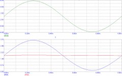
To me the waveform of the output signal looks ok 🙄 but if you have concrete objections, go ahead.

Greetings, Bernhard
Bernhard said:
Andrea,
which waveforms ? What surprises ?
The fets on the higher supply +rails for example work even @ idle, they switch off only on negative output voltage, then the 6V rails take over, but also that could be changed...
To me the waveform of the output signal looks ok 🙄 but if you have concrete objections, go ahead.
Greetings, Bernhard
I foresee problems when the fets turn on/off and also when the diodes turn on/off.
Also Class AB amps don't show waveform problems but we go for Class A because it sounds better.. 😉
I don't want to criticize, I just point out what I fear could be a problem.
On the other side all I can say is "go for it", build it and tell us how it sounds.. simulations can't tell us that!
Cheers
Andrea
I've built a few which run like this conceptually, and they can
sound quite good, but there is always a glitch in the distortion
waveform when the "cascode" transistors switch on and off,
putting a bit of a fly in the ointment.
sound quite good, but there is always a glitch in the distortion
waveform when the "cascode" transistors switch on and off,
putting a bit of a fly in the ointment.
Nelson Pass said:I've built a few which run like this conceptually, and they can
sound quite good, but there is always a glitch in the distortion
waveform when the "cascode" transistors switch on and off,
putting a bit of a fly in the ointment.
It should be no problem to built it in a way that the cascode fets are always "little bit on".
And how about small caps across the diodes and the cascode
fets ?
Isn't it worth to fight for less heat ?
- Home
- Amplifiers
- Pass Labs
- The Aleph-X