

Netlist said:
I guess you mean the -10.16V?
Should be Ok IMO. In the original Grey's sim it also is -10.17V.
Taking in account a supply of -15V, source resistors of 0.22ohm give you -14.58V. Then the Gate is fed with (-14.58V) - (-10.17V) = 4.41V Vgs.
Or I'm I missing something?
/Hugo - Had his Grill-and-Chill yesterday. 😎
Hugo
That's what SE calls a "brain fart". Sorry.
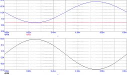
I put together a quick circuit, it works fine, I need to tweak the voltage source as the frequency response doesn't impress me at all therefore the assumption is that I screwed something up.
How is your freq response look like?
Bernhard,
I'll have a closer look at your posted schematics.
I also will try to read the A75 article. Looks like there a tremendous amount of valuable info there.
Grataku,
I can't tell you anything about the response of the circuit. It simply doesn't work.
/Hugo 🙂
I'll have a closer look at your posted schematics.
I also will try to read the A75 article. Looks like there a tremendous amount of valuable info there.
Grataku,
I can't tell you anything about the response of the circuit. It simply doesn't work.
/Hugo 🙂
Netlist said:I'll have a closer look at your posted schematics.
Netlist,
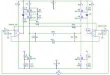
its very simple, R46 and D1 shift the gate voltage of M6 to a higher value against the gate of M7.
As both Fets are source followers, the gate voltages appear shifted on the sources and the drain-source voltage of M7 is held constant.
R56 just compensates a ~4V offset on the output of the op amp x1 that would limit voltage swing otherwise.


Netlist said:
Grataku,
I can't tell you anything about the response of the circuit. It simply doesn't work.
/Hugo 🙂
Hugo,
I haven't read the a75 article, good to know you found it interesting. I'll print out the a75 today.
Oh, It doesn't work?
Ok here is what I have with the same number as your schematic: simple differential with cascodes and open loop.
10k at the input 10k to gnd of the gain mosfet. The CCS has a 1 500 ohm tpot in place of r24,26,59.
r23,25 =500ohm
r55,56 1.5k
r51,52= I played with values of zeners from 5.1 to 9.1 they all seem to do something. No idea of what's best.
I think I got something like 4 ma running through the cascode reference.
NO r53,54
A few stupid observations: the gain increases with increasing bias up to a point after which it starts to distort. I am running like 12ma bias per side, I think.
The voltage on the loads is unbalanced, i didn't match the mosfets. Looking on the scope the square wave looks alright up to ~70kHz after which it starts to tank.
I'll remove the cascode and see what a regular diff does later.
grataku said:I played with values of zeners from 5.1 to 9.1 they all seem to do something. No idea of what's best.
The smaller the zener value ,more the dissipation goes to the cascode fet/bjt.
I think this is the right way to go,because the cascode device does not amplify the signal.
More probably the BJT is what we need to implement cascode at the diff pair and get the circuit working in terms of absolute DC.
Shouldn't we try to operate all mosfets in there most linear region? Or is it of no importance anymore for the diff-pair when cascoded?stefanobilliani said:The smaller the zener value ,more the dissipation goes to the cascode fet/bjt.
I think this is the right way to go,because the cascode device does not amplify the signal.
More probably the BJT is what we need to implement cascode at the diff pair and get the circuit working in terms of absolute DC.
Till now, I didn't use BJT's mainly because I read somewhere that Nelson didn't like the sound.
Of course it's worth a try.
Grataku,
I tried your setup but couldn't make it work with zeners.
Meanwhile I did some other tricks and finally the circuit seems to work now. (never build it, only sim)
Looking at the post with the picture of the schematic you will see a major mistake, apart from R53/54.There is one junction between the drain of the left cascoding mosfet and R23 that should not be there.
/Hugo
Netlist said:
Shouldn't we try to operate all mosfets in there most linear region? Or is it of no importance anymore for the diff-pair when cascoded?
/Hugo
In the power region (
see Zen V4 cascoding thread ) the gain power mosfet is happy with 2 volts drain-source;
The biggest dissipation goes at the cascode power mosfet.
Since cascode is not considered a gain stage , it is possible think at the linearity as a function of 2 devices.
Hugo,
I had noticed the problem with your schematic only later last night. I thought we were talking about a real circuit. 😉
I can confirm it works.
Stefano,
what type of LED did you use for yor schematic with bjts? What is the drop across them?
I think I have ~5 V DS on the gain mosfet in the end. Too much?
I did notice some effects on the frequency response changing the voltage source but it was late last night. This would be a perfect behavior to simulate.
grataku said:
Stefano,
what type of LED did you use for yor schematic with bjts? What is the drop across them?
I have not build that circuit , but in my Aleph ono I used led with a voltage drop of 2 volt .
grataku said:
I'll remove the cascode and see what a regular diff does later.
I did exactly what the theory says. Put at least 2V across the gain device. It is now 2.02V
Trimmed resistors so the voltage is exactly -2V at the gates of the cascodes.
All I get is a nice oscillating amp.


As this is only the sim and you can confirm that things work in real life, I'm happy.
The biggest challenge now is the measurements with and without cascode.
I'm really interested in them.
/Hugo
Attachments
If the gate of the gain fets should be at 0volt -absoluteDC right?-
I wonder how theyr drains may be at +1....
If the gate of the gain fet is at Ovolt then its source will be at +3.5
Try Set the cascode gate at a potential that leaves the gain fet drain at -1 volt.
I wonder how theyr drains may be at +1....
If the gate of the gain fet is at Ovolt then its source will be at +3.5
Try Set the cascode gate at a potential that leaves the gain fet drain at -1 volt.
Hugo,
did you already look at my cascode (?) ?
It works perfect on the sim.
In your circuit are M9 and M11 the cascode Fets ?
If yes, how should that work ?????? No connection to the signal...
Unfortunately I never had a look at the alephx and it will take some time for me to find orientation in that circuit, also there is some breaking news...
Please read all !!!!!!!!!!!
If this is true, i found Atlantis...
Basic circuit is a single ended classA monolytic susy with 15V rails and static current source for simplicity.
It idles @ 1.85A per Fet and dissipates 110W.
Modified circuit still operates in single ended classA and still idles @ 1.85A per Fet and still has static current sources.
No kidding:
The circuit dissipates only 60W 😀
And this is just first try, no tweaking yet.
I believe it can go down much further.
Schematic soon...
Stefano
The picture is not the best I have but:
Take a look at the gates of the gain devices: 2.71mV.
This is not 0V but close to.
The drain of the current source mosfet is at 3.05V.
The drain of the gain device is at 1.05V.
3.05V - 1.05V is 2V across the gain device.
I can change the gate voltage quite a lot without effect on the source voltage. I tried 20mV without change.
No way I can do that without a complete unbalance of the other voltages. Especially the 2V over the gain devices.
/Hugo - wonders if his brain 'farted' now?
Bernhard
The AlephX is such a monster and I begin to realize that it took already more than 6 months of my life.
I'm happy with the results AKA the music it produces but I find myself again in a state of no return with that amp.
So the answer to your question is no; I didn't look at your cascode, but I will.
Indeed, M11/9 are the famous cascodes. 🙂
The picture is not the best I have but:
Take a look at the gates of the gain devices: 2.71mV.
This is not 0V but close to.
The drain of the current source mosfet is at 3.05V.
The drain of the gain device is at 1.05V.
3.05V - 1.05V is 2V across the gain device.
I can change the gate voltage quite a lot without effect on the source voltage. I tried 20mV without change.
Try Set the cascode gate at a potential that leaves the gain fet drain at -1 volt.
No way I can do that without a complete unbalance of the other voltages. Especially the 2V over the gain devices.
/Hugo - wonders if his brain 'farted' now?
Bernhard
The AlephX is such a monster and I begin to realize that it took already more than 6 months of my life.
I'm happy with the results AKA the music it produces but I find myself again in a state of no return with that amp.
So the answer to your question is no; I didn't look at your cascode, but I will.
Indeed, M11/9 are the famous cascodes. 🙂
 OK!It is midnight here , and I woke up at half past4 AM!
I used cascode with SOZ and ZenV2 without problems ...
😴Indeed, time to sleep here too.stefanobilliani said:
I used cascode with SOZ and ZenV2 without problems ...
See you all (maybe) tomorrow.
/Hugo 😉
- Home
- Amplifiers
- Pass Labs
- The Aleph-X