http://www.passdiy.com/pdf/A75p1.pdf
Some older writings are listed under Legacy Projects on Pass DIY site.
Some older writings are listed under Legacy Projects on Pass DIY site.
Thanks for the link.
The biggest problem when trying to cascode parts of the Alephx
is exuberant absolute DC.
Tried all kind of ways to eliminate the DC, it wont disappear.
Changing resistors in the current source or others who influence the problem only result in excessive negative or positive DC.
Even a slight change in value can for example change it from -10 to +9 or whatever high DC value.
Still don't get the trick of cascoding, so if anyone has ideas how to do it, please post them.
/Hugo 😕
😕
The biggest problem when trying to cascode parts of the Alephx
is exuberant absolute DC.
Tried all kind of ways to eliminate the DC, it wont disappear.
Changing resistors in the current source or others who influence the problem only result in excessive negative or positive DC.
Even a slight change in value can for example change it from -10 to +9 or whatever high DC value.
Still don't get the trick of cascoding, so if anyone has ideas how to do it, please post them.
/Hugo
😕
Bernhard said:I'll make a big big poster of that and hang it on the wall
Quote:
Maybe combining classA with the casode will be even better? 🙂
stefanobilliani said:I would prefear to cascode the diff pair first , before of do it for the power section.
Comments are welcome🙂
Do the bjt work better here? I was thinking to use all mosfets for also use a single voltage source for their gates (each with its usual 220 ohm resistor) to get more of a symmetric differential.
Maybe you should check this thread?😉
http://www.diyaudio.com/forums/showthread.php?s=&threadid=3398&highlight=cascode
http://www.diyaudio.com/forums/showthread.php?s=&threadid=3398&highlight=cascode
Reading Syl's thread about the sound of cascodes leaves me with mixed feelings.
There are nice technical explanations but the sum of the posts seems to tell us: "Don't use cascodes unless you really need them".
On the other hand, Nelson very soon will present us the cascode Zen-amp. Would he do it if there were no benefits in doing it? I don't think so.
We will end up saying: Like the sound? Use them and vice versa.
There is of course the technical challenge that could be a lot of fun
(and frustration ) for many people.
Personally I have no preference in how to implement a cascoded
diff-pair. Symmetrical or not, the resulting sound will be the judge.
/Hugo
There are nice technical explanations but the sum of the posts seems to tell us: "Don't use cascodes unless you really need them".
On the other hand, Nelson very soon will present us the cascode Zen-amp. Would he do it if there were no benefits in doing it? I don't think so.
We will end up saying: Like the sound? Use them and vice versa.
There is of course the technical challenge that could be a lot of fun
(and frustration
) for many people.Personally I have no preference in how to implement a cascoded
diff-pair. Symmetrical or not, the resulting sound will be the judge.
/Hugo
Netlist,
I have learned to be skeptical of opinions that I haven't verified in person. I have been surprised more than once. I like the idea of cascodes. I am too ignorant of electronics but I should have tried it a long time ago since the circuit has been around for longer than I have.
I read a few things about it. Intuitively, it seems to make sense. I like the spectral analysis that Nelson showed in his article.
Feedback has it's drawbacks too, for example, but it can be done right and sound great.
Grataku, I agree, if we don't try we will not know.
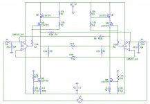
That's why I spent a few hours more and came up with this.
I managed to get rid of the DC. A couple of mV is easily trimmed if necessary.
Now can some cascode guru tell me what's wrong with the input diff-pair and cascoding mosfets? (All irf9610) Why do the four mosfets not turn on? The drawing is a bit difficult to read. It shows the status
of all mosfets: HOT, SATurated, LINear and the voltages.
/Hugo
Attachments
stefanobilliani said:Hey...!
What are those R53 and R54
Let them out, please.
I did. Probably a misinterpreted sentence from Nelson saying to 'load the Drain's with 1k or so'.
stefanobilliani said:The gates of the "cascode" fets should be at a higher voltage ,something like -5 volts.
I guess I'll need another way to implement this thing.
No way to make this work. With cascode gate voltages of -5V and diff-pair gate voltages of -1.94 all Mosfets are on. But then again the DC is untamable:7.57V absolute DC. Fiddling again with the DC adjustments results in shutting down the mosfets.
Thanks for the help anyway.
/Hugo - not giving up...yet. 🙂
BTW: how come my .zip file turned into a picture in previous post?
Netlist said:BTW: how come my .zip file turned into a picture in previous post?
I'm guilty. Zip files are just too much of a pain to deal with and IMO ruin the flow of the thread... so any time i can i convert them to a displayable picture (the gif file you zipped only needed to be made 150-some pixels narrower).
dave
It's OK, don't feel guilty 😉planet10 said:I'm guilty
dave
I was wondering if it was the Sunday evening wine or me...
Turned out to be you!! héhé.
Sometimes I zip files thinking to save bandwidth and load-time for 56k-ers, if any.
/Hugo - Just filled up his glass again. 😉
Netlist said:
I did. Probably a misinterpreted sentence from Nelson saying to 'load the Drain's with 1k or so'.
I guess I'll need another way to implement this thing.
No way to make this work. With cascode gate voltages of -5V and diff-pair gate voltages of -1.94 all Mosfets are on. But then again the DC is untamable:7.57V absolute DC. Fiddling again with the DC adjustments results in shutting down the mosfets.
Thanks for the help anyway.
/Hugo - not giving up...yet. 🙂
BTW: how come my .zip file turned into a picture in previous post?
Hugo,
thanks for taking the time while other are out grilling and chilling.
I noticed the 11 V across r23 and 25. WHy is that so high? That could easily cause the conduction mismatch and the high DC.
I guess you mean the -10.16V?grataku said:
I noticed the 11 V across r23 and 25. WHy is that so high?
Should be Ok IMO. In the original Grey's sim it also is -10.17V.
Taking in account a supply of -15V, source resistors of 0.22ohm give you -14.58V. Then the Gate is fed with (-14.58V) - (-10.17V) = 4.41V Vgs.
Or I'm I missing something?
/Hugo - Had his Grill-and-Chill yesterday. 😎
Netlist said:Sometimes I zip files thinking to save bandwidth and load-time for 56k-ers, if any.
gifs and jpgs are already compressed so zipping usually saves nothing and can even add sometimes.
dave
Some time ago I had the idea to put Fets in series, but for other purpose: To half the voltage across each transistor and thus half the power dissipation per Fet.
So it would be possible to have much higher bias per Fet and stay in the linear area.
With very little mods this may be does not look like cascode, but works like.
See schematic.
Voltage swing across the lower Fet is only 1/20 of voltage swing of the upper Fet.
I also tried to connect a zener from the gate of the cascode Fet to the output and a resistor from the gate of the cascode Fet to the + rail.
Did not work, no idea why...
Attachments
- Home
- Amplifiers
- Pass Labs
- The Aleph-X