Wow! It seems everything can be cheat-chatted to death, even ohms law. This thread is turning into talk radio. The only guy that has measured something seems to be Peter and his numbers don't correspond to mine. I am finally getting my differential probe next week, I will post a complete set of measurements of power as function of both rails (from 12V to 20V) and load R (4 and 8 ohms).
It's going to require re-adjusting the pots for each V level (and the current gain) a painful job but someone's got to do it, so we'll finally be able to compare it to the berenk___whatever spreadsheet. Depending on how I feel I may remove the patented current gain and see what happens.
It's going to require re-adjusting the pots for each V level (and the current gain) a painful job but someone's got to do it, so we'll finally be able to compare it to the berenk___whatever spreadsheet. Depending on how I feel I may remove the patented current gain and see what happens.
AudioFreak
wuffwaff
If you understood this as you claim, you would have mentioned it in this post when you put forward your FIRST power output calculation. If you had, your output calculations would have been double. At the risk of being sinbinned (I have noted this is your style when other members point out your foolishness) I politely request that you abstain from reading or addressing my posts in the future. You really don't have a clue.1) It is a bridged amp
wuffwaff
Why use a number that doesn't reflect the reality of what we hear?.....just joking. both formulas apply, use the one where the power is less.
Grataku:
Ohms law is Ohms law, but I wonder, how Nelson got more then 30 W at 4 ohm before clipping with 2 A biased The Zen Variations - Part 2?
😕
Ohms law is Ohms law, but I wonder, how Nelson got more then 30 W at 4 ohm before clipping with 2 A biased The Zen Variations - Part 2?
😕
Peter Daniel said:
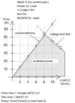
My Aleph X is completely stripped unit, without active current gain circuit and the rails are around 15V DC.
Peter, why did you disable the 'active' part of the current source.
When reading the Zen-part2, Nelson writes:
Figure 7 shows a comparison of the distortion vs power of the circuits of Figure 2 and Figure 6. It's a pretty straightforward result: the distortion drops by a factor of about 10.
http://www.passdiy.com/projects/zenv2-4.htm
Or does this not apply to the AlephX?
I guess you liked the sound better.
/Hugo 🙂
nania said:AudioFreak If you understood this as you claim, you would have mentioned it in this post when you put forward your FIRST power output calculation. If you had, your output calculations would have been double. At the risk of being sinbinned (I have noted this is your style when other members point out your foolishness) I politely request that you abstain from reading or addressing my posts in the future. You really don't have a clue.
Hey no need to hit below the belt there. No, I wont sinbin you for that (Although if I had received a complaint from another member who'd received your treatment as I just have, given that you dont have a leg to stand on with your claims, you would be sinbinned. Given that I cant speak for the other moderators, I cant give you a blanket promise that you wont be sinbinned by one of them if they deem it appropriate.). I'm a big boy, I can handle a bit of constructive criticism. As a member, I would however ask that you tone it down a little and try and be constructive rather than completely unwilling to listen and learn (or perhaps all you need to do is stop and think and it will all become clear). If not for my sake, please do it for the sake of the community.
If you care to go read that post you quoted along with the later post/s I made with calculations, you'd see that they all say the same thing with the exception of slightly different idle current. All my calculations are sound for this amp and you'd see that they have all hovered very close to that measured by Peter himself. We know that we are current limitted so we simply work out power calculations from there. Ohm's Law is Ohm's Law and it's really that simple.
In the interest of helping you work out where your calculations fail to match reality, perhaps you'd like to work through your calculations in a post so we can all see how you get your numbers.
jarek said:
how Nelson got more then 30 W at 4 ohm before clipping with 2 A biased The Zen Variations - Part 2?
My understanding of the key point:
- When Zen (and Aleph) has no Aleph current gain circuit, the maximum output current is independent of the load impedance.
- But, when it has Aleph gain current circuit, the max output current is dependent upon the load impedance to certain degrees.[/list=1]
Therefore, there are differences in power calculation between Case 1 and 2.
JH
Netlist said:
Peter, why did you disable the 'active' part of the current source.
Or does this not apply to the AlephX?
/Hugo 🙂
A quote from the Monolithic SuSy Thread by Nelson Pass
""""""""""""""""""""""""""""""""""""""""""""""
I would have to offer up the notion that an Aleph current
source would be considered a form of current feedback by
itself, although not in the sense you mean.
""""""""""""""""""""""""""""""""""""""""""""""
It seems that the Aleph current source is the heart of the Aleph-x,
If we disconnect the active part we return to a constant current source , like a Zen for instance.
What is the difference in the Supersimmetry tecnique doin' this? 🙂
jh6you said:
My understanding of the key point:
- When Zen (and Aleph) has no Aleph current gain circuit, the maximum output current is independent of the load impedance.
- But, when it has Aleph gain current circuit, the max output current is dependent upon the load impedance to certain degree.[/list=1]
Therefore, there are differences in power calculation between Case 1 and 2.
JH
Not quite.The current gain is simply the ratio of Idle Current divided by Peak Current and is independant of load impedance etc. In a normal single ended amp biased by a constant current source, Idle Current = Peak Current but with an Aleph with AC Current Gain = 50% The peak current avialable is twice that of the bias current.
I got intrigued by the post from Ric Shultz here: http://www.diyaudio.com/forums/showthread.php?s=&postid=107592#post107592 and decided to try the Aleph without active current gain. As the power wasn't the issue (midrange, tweeter amp in bi-amped system) and I was never concerned much with distortion numbers, I didn't see much reason to keep extra circuitry at the output. So I did it and my impression was that the effect wasn't that big. But maybe I should compare it again?😉
'another power'
From The Zenn Variations – Part 2:
‘Instead of the infinite impedance represented by an ideal constant current source, this new variation has a negative impedance equal to twice the load impedance. If the load is 8 ohms, the current source will have a -16 ohm impedance, and the active portion of the amplifier will think it is driving 16 ohms. The reactive portion of the loudspeaker is similarly mirrored in the this manner so that it accurately creates a negative ghost of the load.’
Is it is?
jarek said:From The Zenn Variations – Part 2:
‘Instead of the infinite impedance represented by an ideal constant current source, this new variation has a negative impedance equal to twice the load impedance. If the load is 8 ohms, the current source will have a -16 ohm impedance, and the active portion of the amplifier will think it is driving 16 ohms. The reactive portion of the loudspeaker is similarly mirrored in the this manner so that it accurately creates a negative ghost of the load.’
Is it is?
Yes that explains why we get an improvement in distortion figures but doesn't really explain the AC Current Gain which is what most of the confusion seems to be about.
AudioFreak said:
with an Aleph with AC Current Gain = 50% The peak current avialable is twice that of the bias current.
+ more depending on the voltage across the load.
The current sensing resistors and the load impedance are in series.
Don't you think so?
JH
jh6you said:
+ more depending on the voltage across the load.
Put simply, No.
I might answer this in more detail at another time but it's past 1am here and time for sleep.... In the meantime, you might like to read the Zen-V2 article as well as the Aleph patent.
Good Night.
AudioFreak said:
Put simply, No.
Good morning.
You are right. Not + more, but + 0.
When the output peak current reaches double the idling current, the voltage figure across the Source resistor is locked.
Therefore, the size of peak current is independent of the load impedance whether it has the constant or Aleph current source.
JH
PS. It is pity that I have no copy of the Aleph patent.
You've got it 🙂
I might also point out that given that the sensing resistor/s is in series with the load, the feedback to the current source is relative to the current thru the load not the voltage across it as you stated a couple of posts back. The sensing resistor/s would have to be in parallel with the load to give feedback dependant on the voltage across the load. In any case, the peak current is fixed.
I might also point out that given that the sensing resistor/s is in series with the load, the feedback to the current source is relative to the current thru the load not the voltage across it as you stated a couple of posts back. The sensing resistor/s would have to be in parallel with the load to give feedback dependant on the voltage across the load. In any case, the peak current is fixed.
Hi, JHjh6you said:
PS. It is pity that I have no copy of the Aleph patent.
Could this help?
http://patft.uspto.gov/netacgi/nph-...,376,899.WKU.&OS=PN/5,376,899&RS=PN/5,376,899
http://patft.uspto.gov/netacgi/nph-...,710,522.WKU.&OS=PN/5,710,522&RS=PN/5,710,522
/Hugo - good morning too 😉
What kind of gauge (AWG) wire would you use to wire the mosfet's to the PCB's? I will run a total of 7A bias per channel (3.5A per X side) to 4 mosfet's per set (16 in total for one channel). What does Nelson use for his XA200 to wire? I have looked at the pictures on page 39 of this thread but it is hard to guess what he is using?
I wanted to use one wire of a 'stripped' Kimber 8TC cable per 4 mosfet's. This is about AWG 18 (0.82 mm^2) . I also thought of twisting 2 of these wires for a total of AWG 16 (1.6 mm^2) but this is a lot of work...
I need about 25cm to 30cm of wire to do a full point 2 point wiring from all the mosfet's to the PCB.
1 meter AWG 18 has a 0.020 ohm per meter. V = I * R = 7 * 0.020 = 0.14V per meter = 0.035V per 25cm * 7A = 0.245W
What is recommended?
Edwin
- Home
- Amplifiers
- Pass Labs
- The Aleph-X