Nania,
the x is just a you said "two Alephs bridged". Each Aleph still behaves like he should and still has an ac-current gain just as if he were alone.
The Aleph X wastes just as much power as a normal Aleph with the same output power. The only difference being the supply voltage (halved) and bias current (doubled) as in any bridged amp.
So the Aleph X has two active current sources wich both should be set to the same value and can be varied as you like.
william
Peter
If I recall correctly, your Aleph-X was highly optimized and many parts of the original circuit were not included. Using the last Aleph-X boards as a reference, can you tell us which of the resistor locations were NOT populated? According to my calculations, your Aleph-x should be making around 75W into 3.75 ohms which is a fourfold increase over the measure you provided. Is it possible that the way you measured was faulty?
If I recall correctly, your Aleph-X was highly optimized and many parts of the original circuit were not included. Using the last Aleph-X boards as a reference, can you tell us which of the resistor locations were NOT populated? According to my calculations, your Aleph-x should be making around 75W into 3.75 ohms which is a fourfold increase over the measure you provided. Is it possible that the way you measured was faulty?
There is no way I made mistake with measurements. I didn't change any critical parts values with regard to power (except for active current gain) and after reading the whole Aleph X thread, this was something I actually expected.😉
If you calculate the required bias into 3.75 ohm to get full power with 15V rails, you will know why mine is so low. 'High power Aleph-x' thread has some good examples how to do it.
If you calculate the required bias into 3.75 ohm to get full power with 15V rails, you will know why mine is so low. 'High power Aleph-x' thread has some good examples how to do it.
Peter
Here is how I calculated your output power:
A 15V rail swing will peak around 30W into 7.5 ohms. If we want power not to wilt into 3.5 ohms (ie: scale up linearly with lower impedences), we need to deliver 68.57W peak. The 68.57W represents I^2R so if we divide 68.57 by 3.5 we are left with the required bias current squared. This means that all we need is 4.43A of total bias on the output mosfets before power output fails to scale up linearly with a falling impedence. Four output mosfets will make 4.43A if they each carry 1.1A of the current burden. In order to get 1.1A through each mosfet, you need 450 milliohm source resistors. In the above example, each mosfet will dissipate around 18W so each channel will dissipate around 150W. Your amp is using twice as many mosfets than were required for power to scale up linearly but since your resistor value is higher your current delivery is slightly reduced. It is still sufficiently high at 7.14A to insure that the power will scale linearly as the impedence lowers to 3.5 ohms so this leads me to conclude that your amp is outputting around 21Wrms into 7.5 ohms and around 48Wrms into 3.5 ohms. Please tell me where you see a fault in my calculations.
Peter
As I stated earlier, your amp as you described it should be able to deliver 75Wrms before it fails to deliver more power into a dropping impedence and that will happen at around 2 ohms with 15V rails. I guess you could say that it will "Peter out" at around 75W if your power supply can deliver it 😉
Are you sure that you didn't lose track of which resistors you used? It looks like your numbers match mine when you turn them around and account for circuit parasitics.
nania said:
Please tell me where you see a fault in my calculations.
Peter's data: max 43W for 7.5ohm load and max 19.7W for 3.75ohm load.
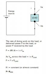
Let's try to simplify the thinking.
This amp gives flow of the same ac current for the same input, independent of the load impedance. And, Wattage = I x I x R. Therefore, wattage for the 3.75 ohm load = 43 x 3.75 / 7.5 = 21.5W.
21.5 are close to the measured 19.7.
JH
jh6you
Well, that is misleading because the same current to a lower impedence MUST make more voltage and therefore more power
The only way this amp could make those numbers with a 3.75 ohm load is in brick wall clipping mode.
Well, that is misleading because the same current to a lower impedence MUST make more voltage and therefore more power
The only way this amp could make those numbers with a 3.75 ohm load is in brick wall clipping mode.
???
The same current, say, 3A.
Load A: 8 ohms.
Load B: 4 ohms.
Fomula for voltage = I x R
V across A: 3 x 8 = 24V
V across B: 3 x 4 = 12V
12V > 24V ...!?!?
Please help me please...
JH
The same current, say, 3A.
Load A: 8 ohms.
Load B: 4 ohms.
Fomula for voltage = I x R
V across A: 3 x 8 = 24V
V across B: 3 x 4 = 12V
12V > 24V ...!?!?
Please help me please...
JH
Now, to make nania even more confused, I also measured the power of my LM3875 based Gainckone amp. With rails at +/-37 V DC the power into 7.5 ohm was measured at 50W and into 3.75ohm it was less than 30W 😉
nania said:jh6you
Well, that is misleading because the same current to a lower impedence MUST make more voltage and therefore more power
The only way this amp could make those numbers with a 3.75 ohm load is in brick wall clipping mode.
It's the other way around nania. Given a CONSTANT VOLTAGE into decreasing load impedance, CURRENT INCREASES to give more power. If current is fixed, LESS VOLTAGE will be dropped across the lower impedance load and therefore LESS POWER delivered. It's all about OHM's LAW.
Peter
Why would you think your gainclone example would confuse me when it illustrates exactly what I'm talking about? If you look at the output curves on the LM3875 chip, the brickwall clipping that I mentioned is illustrated perfectly. I believe the chip has current protection which creates that peculiar response to impedence. The Aleph-x and many other amps don't have such a dramatic dropoff when faced with a lower impedence. The reduction in power is a fiction, more acoustical power results from the lower impedence so the numbers are misleading.
Why would you think your gainclone example would confuse me when it illustrates exactly what I'm talking about? If you look at the output curves on the LM3875 chip, the brickwall clipping that I mentioned is illustrated perfectly. I believe the chip has current protection which creates that peculiar response to impedence. The Aleph-x and many other amps don't have such a dramatic dropoff when faced with a lower impedence. The reduction in power is a fiction, more acoustical power results from the lower impedence so the numbers are misleading.
nania said:I believe the chip has current protection which creates that peculiar response to impedence.
Wouldn't that be the same with Aleph X , when bias is fixed?
Peter Daniel
No, the Aleph-X power rolloff is much more gradual. Given the 7.14A of bias current available you can continue to deliver more apparent power into a lower impedence until you reach around 75W and then you will hear the hard clipping begin similar to what is illustrated in the gainclone power output curves if that is where you've set your gain because that is the point of current starvation. If your music signal has very large dynamic jumps you will notice it even sooner as distortion but the output curve won't look like the LM3875 driven past its internal current capability. At 48Wrms it'll produce the source signal as cleanly as it would at 21W. The bias is fixed but the power is not so the voltage is a useless indicator of the acoustical power achieved. That can only be measured by the speaker coil displacement or with the method I have provided IMHO. Voice coil impedence is not a fixed resistance where power is measured by the heat dissipated in it. If you are dissipating heat in your speaker coil, you are probably already experiencing sonic degradation or worse.
No, the Aleph-X power rolloff is much more gradual. Given the 7.14A of bias current available you can continue to deliver more apparent power into a lower impedence until you reach around 75W and then you will hear the hard clipping begin similar to what is illustrated in the gainclone power output curves if that is where you've set your gain because that is the point of current starvation. If your music signal has very large dynamic jumps you will notice it even sooner as distortion but the output curve won't look like the LM3875 driven past its internal current capability. At 48Wrms it'll produce the source signal as cleanly as it would at 21W. The bias is fixed but the power is not so the voltage is a useless indicator of the acoustical power achieved. That can only be measured by the speaker coil displacement or with the method I have provided IMHO. Voice coil impedence is not a fixed resistance where power is measured by the heat dissipated in it. If you are dissipating heat in your speaker coil, you are probably already experiencing sonic degradation or worse.
Nania,
Perhaps you need an explaination as to how Peter's amp functions.
1) It is a bridged amp
2) Each of the 2 sides are made from single ended amps biased by constant current sources.
3) There is approx. 7Amps total bias
Given those facts, each of the single ended amps have a bias current of 3.5Amps. In bridged configuration, 1 amplifier sources current while the other sinks current. So, you can only deliver a peak current of 3.5Amps to the load. Given a sinus wave average current is 3.57/sqrt(2) = 2.47Amps
P=I^2xR
=2.47^2xR
=6.1R
So, you can see that power MUST decrease into lower load impedances.
nania said:If you are dissipating heat in your speaker coil, you are probably already experiencing sonic degradation or worse.
Given that the average driver is less than 1% efficient and a large part of a drivers impedance is due to DCR, there is always alot of heat that must be dissipated by the voice coil.
Audiofreak, Nania,
why don´t you look at the excel sheet I made. It´s very simple and you will see how to calculate the poweroutput of your X. (search for "berekening")
Nania, peak current is not rms current. Multiply by 1.41
Audiofreak, there´s also P=V^2/R. This means power MUST increasewith lower impedances😱 😱
.....just joking. both formulas apply, use the one where the power is less.
william
wuffwaff....
what on earth will we do with you????
Thanks for the offer of the spreadsheet but i'm quite familiar with how the Aleph and Aleph-X amps function.... and yes I've been ignoring a few of the finer points in an effort to make the basic function of the amp simpler for nania to understand.
Of course there is P=V^2/R but given that we are current limitted, and we dont know the voltage without doing calculations, P=I^2xR is the correct formula for the situation .... (I trust you already know that wuffwaff but my recent posts in this thread have been primarily for nania's benefit..... not sure if any of us are getting thru though)
The power
Peter:
As your Aleph X doesn’t have active current gain circuit there is no gain current.
With Aleph’s current source circuit should be more power than in your measuring. I don’t know if I understand right how the current source works. Correct me if I am wrong.
Peter:
As your Aleph X doesn’t have active current gain circuit there is no gain current.
With Aleph’s current source circuit should be more power than in your measuring. I don’t know if I understand right how the current source works. Correct me if I am wrong.
jarek,
That is correct, usually the Aleph current sources would be set for AC Current Gain of 50% so that they are able to supply upto twice the idle current. With Peter's amp he is using constant current sources so there is no AC Current Gain.
That is correct, usually the Aleph current sources would be set for AC Current Gain of 50% so that they are able to supply upto twice the idle current. With Peter's amp he is using constant current sources so there is no AC Current Gain.
- Home
- Amplifiers
- Pass Labs
- The Aleph-X