Do I see a step ahead? Yes, but through a clouded crystal ball. After all, I predicted that terrorists would take out a tall structure back in the early '90s (in the Darwin's Children series), but I pegged the Eiffel Tower, not the World Trade Center. I got it half right. But that's okay, I'm in good company. Orwell called his book 1984.
Don't feel bad. Nostradamus was only about 18%-20% correct.
thanks,
V~
Formulas you might want to remember (meaning the ones that aren't too hard to remember and that you might actually use):
I*R=E (this is where the basic algebra comes in--you can rearrange the formula any which-way you like to tell you what you want to know: E/I=R and E/R=I)
I*E=P (again, algebra allows us to play games: I(squared)R=P, for instance)
F=1/(2*PI*R*C) (some people get flustered by this one, but it's useful enough that you might want to make the effort to commit it to memory--incidentally, this one can also be rearranged to R=1/(2*PI*F*C) or C=1/(2*PI*R*F))
J=CV(squared) (this is the one Nelson used in the post referred to above--you won't need it very often, but it's easy enough to keep in mind--where this comes in handy is apples to apples comparisons of storage at different rail voltages; think in terms of improving your J/W ratio [that's Joules per output watt])
Where:
I= current
R= resistance in Ohms
E= Volts (sometimes you see the formula with V instead of E)
P= power in Watts (sometimes you see the formula with W instead of P)
F= frequency in Hertz
PI= 3.14 (aw, c'mon, you knew that, right?)
C= capacitance in Farads (microfarads is 10 to the minus 6, pico to the minus 12)
J= Joules (as in Verne...uh, just kidding...actually it's a measure of energy)(as an aside, note that the voltage component is squared--this gives tube guys an edge when they're using 550V rails...think about it the next time you're feeling cocky about your 30,000uF caps on 25V rails, a tube guy can do the same thing with a paltry 62uF...and if he goes as far as a whole, whopping 1000uF, you might as well just start crying--face it, you just can't run w' the big dawgs)
Honestly, if I sat and thought about it, I might come up with a few more, but mostly if I need something else I pull out a book and look it up. Books are your friends. Buy a few. Love them. Cherish them. Take care of them and they will take care of you.
Grey
P.S.: The power supply in my main tube amps (ca. 135W/8 Ohms) uses a CLC filter, and yes, Virginia, I have 575V rails and just shy of 1000uF of film caps in the final leg of the filter. And that's not counting the capacitance in the first leg.
Eat your heart out.
Funny you should mention books. I bought Randy Sloane's Amp book off Amazon today.
I have all the mini books from Radio Shack.
This is not the forum for it, but the concept I have the biggest problem with is- what is current and what is voltage. People use the water and pipe anology, but I have too many questions.
I will stop here. This is the A-X thread. Not the "Amp with Training Wheels Design Group thread". 😉
Thanks,
Vince
Well...I just read that voltage is pressure and current is what the flow?
Voltage and current are completely independent of each other.
You can have one without the other, right?
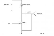
Now, in a simple output of a single transistor. You have voltage coming in to the Drain. You have a smaller voltage going to the Gate. How does the voltage going to the Drain not disrupt the voltage going to the output? It looks like the same path to me.
I just don't understand how voltage and current flow thru a circuit.
Diagram taken from Zen amp article.
Voltage and current are completely independent of each other.
You can have one without the other, right?
Now, in a simple output of a single transistor. You have voltage coming in to the Drain. You have a smaller voltage going to the Gate. How does the voltage going to the Drain not disrupt the voltage going to the output? It looks like the same path to me.
I just don't understand how voltage and current flow thru a circuit.
Diagram taken from Zen amp article.
Attachments
Let me suggest that you read the A75 article available on
www.passdiy.com where there is a discussion about how
Mosfets and current/voltage work from a basic standpoint.
www.passdiy.com where there is a discussion about how
Mosfets and current/voltage work from a basic standpoint.
All right, let's get the quickie out of the way first. The output cap on the Zen blocks DC and lets AC pass. We'll come back to that in a moment.
As for water, we'll start with an ordinary garden hose. It's got one of those pistol grip thingys on the end. (Don't you just love it when I talk technical?) Turn on the water at the faucet. Assuming that you're not squeezing the handle, no water flows, right?
Let's evaluate the situation as it stands right now: We have pressure (aka voltage), but no water is actually flowing. In electrical terms, we have no current. There's water in the hose, ready to flow if only you'd let it.
So what are you waiting for? Let it flow.
Squeezing the handle part-way allows water to flow. You now have pressure/voltage and flow/current. Be careful with the term current because water can have currents too, and it'd be easy to muddy the waters (ahem).
Let's look at this in a little more detail. If you were to use a meter to measure the water pressure inside the hose at this moment, you'd probably find that the pressure has dropped by a small amount. To put this in test bench terms, you'll generally find that the rail voltage drops a bit when you hook a circuit to the power supply. It's pretty much the same thing.
The brass pin that moved when you squeezed the handle went from stopping the flow entirely (infinite resistance) to a more moderate resistance. The flow rate (current) is determined by how much the valve restricts (resists) the pressure (voltage).
So you can have voltage without current. It's the potential to flow. If someone in the house flushes the toilet, the potential...the water pressure in the hose will drop. If the resistance remains the same, the current will fall too--just like in electronics.
Your hand on the handle controls the water flow. You need not get your hand wet. The handle is analogous to the Gate. The voltage at the Gate controls the current between the Drain and the Source without ever getting its fingers wet, if you follow what I'm saying.
It's easier to visualize this in electronics with a tube or a JFET.
You know how your hair sticks to your comb on a dry winter morning? That's static electricity. Like charges repel. Opposites attract. You've heard that. Let's take a look inside a tube for a moment.
The cathode (think: Source) emits electrons. They float around the cathode in a cloud looking for something to do. They're bored. They want to go somewhere. We'll give them a destination by giving the plate (think: Drain) a positive charge. Opposites attract. The electrons, which are negatively charged, start towards the plate/Drain.
But wait...
The grid (think: Gate) stands in the way. And it's got a negative charge. Like charges repel. The electrons are repelled.
So we vary the negative charge on the grid and by doing so we allow the plate to draw more or fewer electrons to itself. Ta da! We have managed to control the electron flow and create a signal at the plate. The operative point here is that it was done with a static charge. No current flows though a grid. Lacking electron "flow" i.e. current, it has effectively infinite resistance.
A JFET works pretty much the same way, but it's easier to visualize electrons flowing through space than through a solid. At least for me it is. So I used a tube for the example.
Back to the capacitor, but keep the static charge thing in mind. You're got two plates staring at each other across a gap. Put a charge on one side (let's say it's negative) and add our magic formula (like charges repel) and Presto!...electrons (the negative guys) flee from the other plate, out into the wire and on towards their destiny. Now if things stop right here (in your mind, play a sound effect of brakes screeching)...you have a DC charge on one side and a single, sharp pulse coming out the other side of the cap. Once that pulse (the amp might go BUMP at turn-on, for instance) is gone, no further current flows. Why? Because those bad-boy electrons on one side scared off all the electrons on the other side. There aren't any more to scare. Well, okay, there are, but let's leave that alone for the moment.
So in other words, caps block DC.
Now, if you change the first plate's charge to positive, then all the electrons come running back and current flows again. And then you change the first plate to negative and they run away, positive and they come back, and so an AC signal can flow through a cap, but DC can't excepting that BUMP at first, which if you think about it, changing from 0V to some steady voltage like, say, 10V, does constitute change, hence AC, at least for an instant.
Grey
Vince,
the hydraulic valve analogy gets even better.
Every type of valve shows a pressure drop, named after the Italian scientist Giovanni Venturi who discovered it using Bernouilli's fluid law.
Different hydraulic valve types have different pressure drop levels.
In the jet engine industry, and every other type of turbine engine, multiple rotors are placed behind eachother to minimise that pressure drop.
Valve pressure drop measuring is used in the medical world to determine heart and circulatory problems, the Venturi effect is also used in every musical instrument type that has valves.
MOSFET valves show a similar effect, Rds times current means voltage pressure drop.
Comparing different kind of valves is like the difference between a Lateral and a Vertical MOSFET, sort of.
Turned fully open, the Rds(on) value of lateral and vertical MOSFETs is very different.
The classic TO3 Hitachi MOSFETs have an Rds(on) of 1 Ohm, compare that to less than 0.2 for an IRFP240, sort of like fluid having to do a straight 90 degree corner movement in a valve.
(i've put my skeeler safety helmet on just in case NP feels like slapping me all across the room this time round)
Is it ok if I put this on a wiki here on diyaudio.com?
I can't be the only person with these questions.
Thanks for taking the time to do this.
Vince
I can't be the only person with these questions.
Thanks for taking the time to do this.
Vince
Fella, if you think it says what it needs to say, then have at it. I just cobbled a few words together in between things at work last night. It took bloody near forever and if you read with an eye for detail, you can see some of the seams where I had to stop and do something else then come back and try to recapture my train of thought...only to find it had derailed in my absence.
Grey
Grey
?
Ok, so the Gate voltage doesn't control the Drain to Source voltage directly. The Gate voltage opens and closes a "valve" in the transistor that in turn controls the Drain to Source voltage. Is that correct?
Is this the misunderstanding where people think electrons come from the positive side, when in fact they are coming from the negative side and run to the + side?
So, as the electrons flow from the Source to the Drain; the lower Gate voltage (AC?) "controls" the higher DC voltage, raising and lowering it. Does this turn Source to Drain into a AC pulse to simulate a Sine wave?
You reverse the whole thing with P-channel Fets or PNP, but there's only N-type tubes, right?
Also, like in the Zen amp, 35v DC is the potential voltage, if you opened up all the way. Correct or not? The resistor then, as a current source, just controls the amount of current you want that part of the circuit to have. Is this correct or not?
Quick, someone get me a breadboard!!
Your hand on the handle controls the water flow. You need not get your hand wet. The handle is analogous to the Gate. The voltage at the Gate controls the current between the the Drain and the Source without ever getting its fingers wet, if you follow what I'm saying.
It's easier to visualize this in electronics with a tube or a JFET.
Ok, so the Gate voltage doesn't control the Drain to Source voltage directly. The Gate voltage opens and closes a "valve" in the transistor that in turn controls the Drain to Source voltage. Is that correct?
You know how your hair sticks to your comb on a dry winter morning? That's static electricity. Like charges repel. Opposites attract. Let's take a look inside a tube for a moment. The cathode (think: Source) emits electrons. They float around the cathode in a cloud looking for something to do. They're bored. They want to go somewhere. We'll give them a
destination by giving the plate (think: Drain) a positive charge. Opposites attract. The electrons, which are negatively charged, start towards the plate/Drain.
Is this the misunderstanding where people think electrons come from the positive side, when in fact they are coming from the negative side and run to the + side?
So, as the electrons flow from the Source to the Drain; the lower Gate voltage (AC?) "controls" the higher DC voltage, raising and lowering it. Does this turn Source to Drain into a AC pulse to simulate a Sine wave?
You reverse the whole thing with P-channel Fets or PNP, but there's only N-type tubes, right?
Also, like in the Zen amp, 35v DC is the potential voltage, if you opened up all the way. Correct or not? The resistor then, as a current source, just controls the amount of current you want that part of the circuit to have. Is this correct or not?
Quick, someone get me a breadboard!!
vdi_nenna said:?
.........
nice link for common guy seeking knowledge .........
http://www.bcae1.com/
where was internet when I was a kid, stealin' and beggin' tiniest particle of woodoo ...........

I hope that this will be useful to you
nice link for common guy seeking knowledge
That is a super cool site!
Thank you!
V~
vdi_nenna said:?
Ok, so the Gate voltage doesn't control the Drain to Source voltage directly. The Gate voltage opens and closes a "valve" in the transistor that in turn controls the Drain to Source voltage. Is that correct?
Is this the misunderstanding where people think electrons come from the positive side, when in fact they are coming from the negative side and run to the + side?
So, as the electrons flow from the Source to the Drain; the lower Gate voltage (AC?) "controls" the higher DC voltage, raising and lowering it. Does this turn Source to Drain into a AC pulse to simulate a Sine wave?
You reverse the whole thing with P-channel Fets or PNP, but there's only N-type tubes, right?
Also, like in the Zen amp, 35v DC is the potential voltage, if you opened up all the way. Correct or not? The resistor then, as a current source, just controls the amount of current you want that part of the circuit to have. Is this correct or not?
Quick, someone get me a breadboard!!
1- Yes. Note, however, that bipolars function differently. In a bipolar, current actually flows through the base. This bothers me greatly because deep down inside I'm programmed to think that grid (think: base) current is a bad thing. If you've got grid current flowing, you're on the verge of disaster--your plate glows bright red and the whole thing goes POOF very quickly. The fact that it's entirely normal for a bipolar just doesn't sit well with me. That's one reason that you haven't seen a lot of bipolars in the circuits I've posted here. It just ain't natural for current to flow through the control pin of a gain device.
2- It's kinda like hot and cold. Hot exists. It refers to a material object with a lot of thermal energy. Cold doesn't really exist, per se, it's just a convenient word we use to describe something that is "less hot."
Likewise, there's negative, which means that there are electrons available, and positive--which isn't really a separate thing; it's just a convenient word to say "less negative."
(Yes, pendants could argue about this for ages, but it's not an inaccurate way to frame things, seeing as how protons aren't mobile in the electrical sense. Plasma isn't part of our audio-related game plan.)
The whole thing about which way current flows gives me a headache. You want to know the truth? I ignore all those silly arrows on schematics, at least in terms of current flow. To me they are just abstract symbols with no real meaning. If I start paying attention to them I get confused. I think of it in the purely physics sense of where the electrons actually are and where they're actually going. I can't bother my poor feeble brain with some arbitrary fiction about current flow. It just bothers me to no end.
3- If it helps, you can think of the signal as varying DC.
(To pendants: SHADDUP!)
4- Right. Tubes only come in the N flavor, because of the aforementioned lack of mobility of protons. Solid state goes at things a little differently and so you can have P-ch devices which act like upside-down N-ch devices.
5- I'm holding a bottle in one hand trying to get Wyatt fed and typing with the other. Don't have a Zen schematic handy. I'll try to get to this one later.
Grey
GRollins said:
1- Yes. Note, however, that bipolars function differently. In a bipolar, current actually flows through the base. This bothers me greatly because deep down inside I'm programmed to think that grid (think: base) current is a bad thing. If you've got grid current flowing, you're on the verge of disaster--your plate glows bright red and the whole thing goes POOF very quickly. The fact that it's entirely normal for a bipolar just doesn't sit well with me. That's one reason that you haven't seen a lot of bipolars in the circuits I've posted here. It just ain't natural for current to flow through the control pin of a gain device.
2- It's kinda like hot and cold. Hot exists. It refers to a material object with a lot of thermal energy. Cold doesn't really exist, per se, it's just a convenient word we use to describe something that is "less hot."
Likewise, there's negative, which means that there are electrons available, and positive--which isn't really a separate thing; it's just a convenient word to say "less negative."
(Yes, pendants could argue about this for ages, but it's not an inaccurate way to frame things, seeing as how protons aren't mobile in the electrical sense. Plasma isn't part of our audio-related game plan.)
The whole thing about which way current flows gives me a headache. You want to know the truth? I ignore all those silly arrows on schematics, at least in terms of current flow. To me they are just abstract symbols with no real meaning. If I start paying attention to them I get confused. I think of it in the purely physics sense of where the electrons actually are and where they're actually going. I can't bother my poor feeble brain with some arbitrary fiction about current flow. It just bothers me to no end.
3- If it helps, you can think of the signal as varying DC.
(To pendants: SHADDUP!)
4- Right. Tubes only come in the N flavor, because of the aforementioned lack of mobility of protons. Solid state goes at things a little differently and so you can have P-ch devices which act like upside-down N-ch devices.
Grey
Just brilliant in its simplicity! Thanks, Grey! 🙂
By the way, if you want an image of how a JFET works, just squeeze the garden hose with your hand. (Yes, I know it's difficult...eat your Wheaties, you wimp.) As you squeeze and release the hose, you modulate the water flow. Simple, eh?
Grey
Grey
GRollins said:By the way, if you want an image of how a JFET works, just squeeze the garden hose with your hand. (Yes, I know it's difficult...eat your Wheaties, you wimp.) As you squeeze and release the hose, you modulate the water flow. Simple, eh?
Grey
I assume that your hand represents the gate, the input signal? The hose-bib (faucet) is the source/drain resistance? I guess the hose is made of rubber that's delicate as a balloon, hence the need for the hose-bib--to have good control over the available pressure and current so as not to rupture the hose.
Great analogy, Grey.
🙂
edit: BTW, this stuff would make an excellent Dr. Seuss type of book for young readers!
- Home
- Amplifiers
- Pass Labs
- The Aleph-X