can't jfet do the "work" alone?till said:I want to come back to JFETs -
http://www.diyaudio.com/forums/showthread.php?postid=112728#post112728
The discussion about JFET frontend did not lead to a "final" schematic.
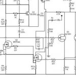
A friend sent me this:
Your shematic shows 2 mors mosfets, that would make the ax a 3 stage amp
Bricolo,
The AX is a 3 stage-Design. In this front-end simply the mosfet IRF510 replaced the bipolars mpsa18 in Grey's design. Without now having had the opportunity to hear fets against bipolars, I read from a lot of sources that an all-fet-amp is much better in sonics than a similar design with bipolars. So, if someone would simulate the high-frequency-behavior of this front-end and if this is OK, it could be the best-sounding version around...
Thanks for posting the circuit.
Blitz, correct me if i´m wrong. The mpsa18 are part of the alpeh current sources feeding the output devices. They don´t affect the signal in any way, they only control the current over R5 / 40.
The differntial pair input is one stage. The bridged aleph output stages are the second stage. 2 stage design. The Jfet input pair doesn´t deliver enough current for the second stage because Jfets doesn´t like a lot of current bias. The 510 are nothing but followers so no voltage gain - no gainstage. If ZenV4 is one stage design the 510 are not a stage, they build one stage with the Jfets.
Do i see this right?
For the advantages of Jfets see some pages before, i gave a link in my posting before. Its intended for usage with hornspeakers >= 100dB/W
Yup, sorry not being clear.
I believe you can have with the V-Types of the 2sj109 nicely 6-8mA Bias through them extending bandwith etc.
I believe in the schematic above the 2sj109 and not the 2sk109 is meant, right ?
I believe you can have with the V-Types of the 2sj109 nicely 6-8mA Bias through them extending bandwith etc.
I believe in the schematic above the 2sj109 and not the 2sk109 is meant, right ?
I believe in the schematic above the 2sj109 and not the 2sk109 is meant, right ?
yes you are right.
blitz,
This looks right, only value of R23 has to be changed to ~3.92K says the the american friend who made the schematic.
please check your email. Till
This looks right, only value of R23 has to be changed to ~3.92K says the the american friend who made the schematic.
please check your email. Till
The 1K resistor was chosen as I would pass 4-6 mA through each device and as we want to have 5V across these resistors, this needs to be adopted.
Can you explain how much current you want/get through the
newly introduced irf510?
Mr Blitz reports no voltage gain so no gainstage.
This I do not understand. Could it be, he means voltage gain of 1?
Then it would qualify as a gainstage, wouldn't it?
In short, until now I have not found a way to make this work.
I am playing with a jfet diff stage at this moment and will try to
finish a simulation in the coming days.
Regards.
It seems to be about 50mA flow through the IRF510. It is a source-follower, so the voltage gain is approximately 1. Mmm... No Miller capacitance, so high frequency distorsion is not added at this stage...rtirion said:Can you explain how much current you want/get through the
newly introduced irf510?
Mr Blitz reports no voltage gain so no gainstage.
This I do not understand. Could it be, he means voltage gain of 1?
Till, from your American friend?
😎
JH
X Aleph vs Aleph Comparisons,
My initial impresssions are much like those before me,
More apparent spark in the upper mid and top end, less mooph/wool in the bass and less warmth across the vocals with the X Aleph.
However warmth may be the wrong word, engaging and more romantic maybe more appropriate for theAleph.
The L100's are very good for bring out the good/bad of a recording and the differences were not sublt, even with on off air broadcasts.
If straight up A/B's are anything to go by, I would say the X Aleph is different but not better and it may come down to application.
Its possible that pure piston range speaker systems may need the more romatic of the two, aka the Rushmore.
No doubt more lengthy analysis will change my resolve.
Ian
Hello Ian,
what about the bottom end (and bass region in general) comparison?
Thanks
Marcello
what about the bottom end (and bass region in general) comparison?
Thanks
Marcello
R19 and R29:
It has been suggested that Grey's values of 68k are incorrect and that we should use 10k to 20k instead. I've tried all three values and must now report that the dc offset is initially lower with the 68k resistors and therefore drops to zero more rapidly. The sound is pleasant with the 68k value and this is where I intend to keep things for now.
Just food for thought,
John
Lowering the value of resistance to ground at the
Gates of the input diff pair affects a couple of things:
It lowers the tendency for common mode offset to
be amplified positively.
It lowers the open loop gain of the circuit, and thus the
amount of feedback.
If the source (preamp, cd player, what-have-you) has
a reasonably low DC impedance and you are DC coupling
the input, this resistor is unnecessary. If you are AC coupling
the input, it is essential.
Clearly there are optimal values for every circuit example
and taste, and the nice thing about it is you can fool
around with the values all you like and note the sonic
differences.
pass/ - he likes different sounds all the time.
I'm using 0.1u coupling caps for high pass (bi-amp setup) and 33k resistors to ground at the gates. I noticed that if I place another set of resistors to ground before the caps (100k) the sound seems to be somewhat cleaner. Any particular reason for that?😉
Could it be that the lower load impedance (now 50k) takes away more of the influence of the interconnect?
And also terminates the input stage capacitance with a lower resistance to GND?
What about an even lower value before and after the cap, like 10-20k?
/Peter (me too 🙂
And also terminates the input stage capacitance with a lower resistance to GND?
What about an even lower value before and after the cap, like 10-20k?
/Peter (me too 🙂
I have less hum.......
Using the 68k resistors, the noise floor is lowered.
I also noticed that the top ends is a bit more crisp sounding.
Using the 68k resistors, the noise floor is lowered.
I also noticed that the top ends is a bit more crisp sounding.
Those would be symptoms of increased feedback.
pass/ - doesn't mind a little feedback now and aqain
pass/ - doesn't mind a little feedback now and aqain
Because the AX is inherently warm/lush sounding, the added crispness to the details on the top end aren't causing it to sound too sterile.🙂
John
John
If you need some 0.20 or 0.25 TO220 caddock to stuff your ver. 1.0 pcb you may want to check this out!
http://diyaudio.com/forums/showthread.php?s=&threadid=10375
http://diyaudio.com/forums/showthread.php?s=&threadid=10375
- Home
- Amplifiers
- Pass Labs
- The Aleph-X