"I was going through withdrawals"
hehe... me too. I'm so dependent on this forum, I was getting bored! Heck, I actually took my soldering iron out of the box and used it! 😀
hehe... me too. I'm so dependent on this forum, I was getting bored! Heck, I actually took my soldering iron out of the box and used it! 😀
Re: ummmm - suggestion
Although, I would rather make my own board. I feel that if a mass pcb order is organized, then the carpenter/wessol board should be looked over and agreed on before the order is taken place.
I am still working on my own board and had some time to work on it some more. Here is my second try at the input stage. It should be more symmetrical then the last version that I posted. I added the ability to jumper the CCS resistor to ground or -V, as suggested by hifizen. I have also reverted to 90 degree corners on the traces in the spirit of the pass labs boards. I wanted to keep a seperate -Vcc and +Vcc input so that different filtering options can be tried.
Any input is appreciated. Good luck on getting the mass pcb order together.
--
Brian
Ken L said:wouldn't our group be better off as a whole to agree on one board as a first version - signed off on, so to speak, by most of the potential users.
Then get that group of boards in use and when the time comes make changes to that board - a 2nd Gen of the same board - with the first board as a standard to go by?.
Off the top of my head, it seems that there would be more potential benefits to having only one version of 1st generation boards out there.
We split the focus of developemental paths and reduce the benefits of group purchasing power if we start off with two versions.
Although, I would rather make my own board. I feel that if a mass pcb order is organized, then the carpenter/wessol board should be looked over and agreed on before the order is taken place.
I am still working on my own board and had some time to work on it some more. Here is my second try at the input stage. It should be more symmetrical then the last version that I posted. I added the ability to jumper the CCS resistor to ground or -V, as suggested by hifizen. I have also reverted to 90 degree corners on the traces in the spirit of the pass labs boards. I wanted to keep a seperate -Vcc and +Vcc input so that different filtering options can be tried.
Any input is appreciated. Good luck on getting the mass pcb order together.
--
Brian
Attachments
Ken,
You have some good points there. However, I think there's nothing explicity <i>wrong</i> with carpenter's board layout, except that it doesn't necessarily meet everyone's needs or wish list. So, for those who want to get building right away, I don't see any reason to stop them, as long as they understand that it's based on an early version of the circuit.
Instead of holding up progress, I think it's better to go ahead and do the "unified" PCB as a separate effort, since it will take some time to assemble the complete schematic, do the layout, and arrive at a generally accepted design. Secondly, I don't think the exact details of the physical layout and component arrangement are too important, so long as they're done by a competent designer. Since carpenter's design is actually just a predecessor to the current bunch of variants, it isn't really a split in the developmental lineage. Any results from construction of his board will be directly applicable to other efforts... as long as the connections are correct, it should work substantially the same as another layout of the same circuit. Given this, I feel it is actually more productive to have more people building the circuit sooner. This will allow us to incorporate changes into the "unified" design sooner. Anyway, the circuit of the unified design won't be much different. I expect it will mostly include footprints for alternative components, or stability elements which may be needed, and some layout differences to make the design a little more flexible.
With respect to group buying power, the primary savings are seen going from single orders to quantities of a dozen or so. Beyond that, the gains are a diminishing return with quantity. So, we shouldn't be sacrificing much in this area.
Re: back from the great diyAudio outage...
That's a heat sink, which is required, because our small ZVP is getting pretty hot. I'm also running the differencial pair at 50 % more current. I believe it may help the sonics.😉
hifiZen said:
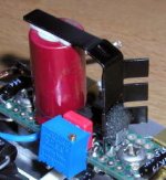
A few pages back, you posted a pic of your P2P wired current source... what's the fuzzy "hair" that your ZVP mosfet is wearing?
That's a heat sink, which is required, because our small ZVP is getting pretty hot. I'm also running the differencial pair at 50 % more current. I believe it may help the sonics.😉
Sure, I see the heatsink, but it looks like your mosfet's got an afro! Is it lint or something? Damping material, maybe... ? Heh, it just caught my attention cuz it looks funny! 😀
The pic I'm referring to is this one: http://www.diyvideo.com/forums/showthread.php?s=&postid=76828#post76828
The pic I'm referring to is this one: http://www.diyvideo.com/forums/showthread.php?s=&postid=76828#post76828
I found it the only reasonable way to mount a heat sink on TO-92 devise. I used 5 min. epoxy to attach the mosfet to the sink. The heat sink is modified standard TO-92. The cap serves as a support. And this baby gets hott.😉
I thought it was smart, not funny.😉
I thought it was smart, not funny.😉
Attachments
Hello,
here is my new alephX pcb VERSION 0.8, I got some inspiration from TVI layout (thank you TVI).
Details:
Based on Grey's original schematic (thank you Gray and Nelson of course)
Modifications:
-back resistors to source of differential pair
-Fred CCS (thank you Fred) with LM329 and J511 (siliconix version 4.7mA). R17 goes to -15V NOT to ground so it's value should be doubled
-Back to back differential pair and space for heatsink on the CCS mosfet zvp3306.
-compensation caps provided on Q3 and Q8 (ce) and between +/- outs and Q4c and Q9c, respectively.
I am sure I am forgetting something.
What it doesn't have:
-Provision for V2 (one should solder a trimpot figure the correct value of resistance, measure it and then substitute the trimpot for a fixed value.
-Input caps
Grounds:
I put the star ground on the middle of the PCB. The ground from the caps should be connected to the lower hole, the upper hole should go to a thermistor to the chassis and AC plug ground.
I can say that the layout is 99.9% symmetrical topology. Lots of effort was put into this. In one case where I couldn't do it I made the traces have identical lenght.
Double sided, metallized through-holes. BIG traces, doubled on both sides.
Later, I am going to make another version with twice the output mosfets for higher bias.
Suggestion for further mods and snide remarks are welcome!
EDIT:
I have made some mods in the ground section and modified the figure 8 motif which was pointless. I am going to bed now. Will make new pics later
Attachments
Nice to read all about Your efforts to realise the board to the AlephX. Just great work!
I am going to rebuild my testversions (a kind of bird nests) of XBOSOZ and XSOZ, and therefore I have to consider how to make my Veroboard and wirering in order to get the most effective noise cancellation from the Xfeedback.
Then my question: Is the use of symmetry better than just to replicate the left side of the layout when makinking the right, thus they will become identical without symmetry?
The reason I ask this is, that the mosfets can´t be set up symmetrically because of their own nonsymmetrical pinlayout. By replicateing - the two halves of the circiut becomes identical, the mosfets included.
I am going to rebuild my testversions (a kind of bird nests) of XBOSOZ and XSOZ, and therefore I have to consider how to make my Veroboard and wirering in order to get the most effective noise cancellation from the Xfeedback.
In Your development of the AlephX board, You are using symmetry between the two halves of the circiut in order to make them identical.Nelson: Make all the parts location and wiring identical in
layout AND location between the two halves of the
circuit. That way all the noise pickup is identical between
the two halves of the circuit.
Then my question: Is the use of symmetry better than just to replicate the left side of the layout when makinking the right, thus they will become identical without symmetry?
The reason I ask this is, that the mosfets can´t be set up symmetrically because of their own nonsymmetrical pinlayout. By replicateing - the two halves of the circiut becomes identical, the mosfets included.
To me, the symmetry means that electrons or current flow through the same distance
from the element to the element in the left half and in the right half. It does not matter
where the elements are and does not matter if their locations are symmetry or not.
JH
from the element to the element in the left half and in the right half. It does not matter
where the elements are and does not matter if their locations are symmetry or not.
JH
jh6you
it definitely should matter to you. By your rationale, if you take a piece of straight wire 1m long and use as is or make a 10 cm diameter coil out of it you get the same electric behavior out of it, right? Wrong.
it definitely should matter to you. By your rationale, if you take a piece of straight wire 1m long and use as is or make a 10 cm diameter coil out of it you get the same electric behavior out of it, right? Wrong.
symmetry of the fields and the electromagnetic environment requires physical symmetry. you can argue magnitude and impact but from first principles you are stuck with the requirement of physical symmetry...as brought out by the previous post's example
rt
rt
Hi Grataku
If you compare that extreme, I have nothing to talk more.
Anyhow, I see your point. But, the coil is an element to me.
JH
If you compare that extreme, I have nothing to talk more.
Anyhow, I see your point. But, the coil is an element to me.
JH
1/137 just beat me to the better explanation I was preparing.
here is a chassis layout as I envision it and the updated PCB whit slight mod to the ground area.
Having symmetry in the circuit is a good thing if you want to balance out the effects of transformer stray flux. Symmetry also should balance out the field generated by the high currents that circulate on this pcb.
By the way, the PCB was done with the ExpressPCB software.
I have to ponder on the circuit some more but in about a week I will send out the file to make a few prototypes.
Attachments
Henrik said:
In Your development of the AlephX board, You are using symmetry between the two halves of the circiut in order to make them identical.
Then my question: Is the use of symmetry better than just to replicate the left side of the layout when makinking the right, thus they will become identical without symmetry?
There is a limit as how much you want to go to the extremes. Doing two separate boards for two halves of the circuit is not convenient, and extra wiring is probably more performance degrading than slight assymetry.😉 Also, we are using only one current source, so which half of the circuit should accomodate it? Or maybe third board would be recommended?😉 Actually that's exactly what I did, but it was p2p effort, which allowed more flexibility. When PCB is considered, take advantage of its convenience and place everything on one board.😉
My Assumption
I am assuming that by symmetry people mean that board has mirror symmetry between the two sides....
rt
I am assuming that by symmetry people mean that board has mirror symmetry between the two sides....
rt
RT
what looks symmetric on the schematic is symmetric on the PCB (as much as it was possible for me). The CCS is not. I tried to keep the displacement along x as small as possible.
what looks symmetric on the schematic is symmetric on the PCB (as much as it was possible for me). The CCS is not. I tried to keep the displacement along x as small as possible.
grataku
and the board symmetry does look great...you can only do so much! This will be fun to build!
I just wanted to be sure that I was using the same definition of symmetry as everyone else was.
rt
and the board symmetry does look great...you can only do so much! This will be fun to build!
I just wanted to be sure that I was using the same definition of symmetry as everyone else was.
rt
Thanks all for Your concern for one not building the AX!
I have never thougt in these terms before, but of cource this has to be considered.
Peter
I didn´t mean to make two Veroboards, that was not what I ment by replicate.
"Also, we are using only one current source" Also, I am using only one resistor (several in parallel).
I consider the tail in both my XBOSOZ and XSOZ as outside the symmetry since they them self don´t have any diffrential or symmetrical behavier, I have shortet the diff. pair sources.
I will place every thing on my Veroboard (one of those fiberglass plates with a lot of holes in an some soldering islands, no PCB) and then make some nice P2P wirering.
Can´t wait to see some pics of Your good work.
- Home
- Amplifiers
- Pass Labs
- The Aleph-X