THD is now 0.00045% after degeneration
I'd be more interested in seeing a FFT plot of the harmonics rather than the absolute THD number.
Also, LSK189 is a fairly expensive part to use for a CCS. Is there something else more affordable that can be substituted?
I built this last year for my SX3700.
2 changes are 47k resistors instead of constant current and IRF240 and IRF9140 biased at 6v. I also added 1n4148 on vas to fix clipping . Sounds great good to know distortion is this low. I am using 9.1k// 1k feedback ratio gain of 10.1 .
2 changes are 47k resistors instead of constant current and IRF240 and IRF9140 biased at 6v. I also added 1n4148 on vas to fix clipping . Sounds great good to know distortion is this low. I am using 9.1k// 1k feedback ratio gain of 10.1 .
So I used improved models: bipolar transistors taking into account the quasi-saturation region, field-effect transistors taking into account the subthreshold current (current in the threshold area). I had to increase the source resistors. Apparently, I have other parameters of the LSK189 transistors. I have achieved approximately the same output cascade currents as you have, as well as the currents of the last differential cascades.


Unrelated question: I see you’re using QSpice. Is it starting to be ready for prime time? I tried it a few months ago and it looked promising, but a little too buggy.So I used improved models: bipolar transistors taking into account the quasi-saturation region, field-effect transistors taking into account the subthreshold current (current in the threshold area). I had to increase the source resistors. Apparently, I have other parameters of the LSK189 transistors. I have achieved approximately the same output cascade currents as you have, as well as the currents of the last differential cascades.
View attachment 1470764
I believe that Qspice is already quite suitable for audio circuitry. Its results are quite reliable. The main thing is to use the right models.But Multisim may miss (not detect) the instability of the amplifier. In addition, Qspice has the ability to model JFET transistors more accurately. In addition to improved modeling in the cut-off area, it allows for more accurate modeling of the initial phase of the volt-ampere characteristics (similar to more advanced models of bipolar transistors, taking into account quasi-saturation).
I'm sure the math is fine. I was just getting annoyed by UI bugs. But those may have been fixed. I should probably give it another shot. And with that, please accept my apologies for hijacking the thread!
I replaced the JFET transistors. I reduced the current through them and reduced the current of the transistors at the output (~85 mA). As a result, the distortion was halved.

I am quite sure that if you try Hann or Blackmann-Harris, the noise floor would be flat. Would depend on FFT length as well.
Hi, Lineup!
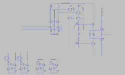
Let's just add cascodes for IPS and VAS, and, of course, driver stage for laterals.
Just a barebones FYI.
Let's just add cascodes for IPS and VAS, and, of course, driver stage for laterals.
Just a barebones FYI.
Attachments
Last edited:
With Microcap, Hanning window, 330mA bias, 4Vpp out, other transistors: BC, BD and Hitachi 2SJ/2SK.

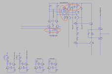
That two-pole compensation is not going to work as expected, as there is no appreciable voltage swing on either side of the CRC networks.
- Home
- Amplifiers
- Solid State
- THD 0.00045% and 15 Watt