That should never happen. You may have taken your ground reference from the wrong spot, or there's a bad ground connection. That's assuming input power is stable, of course.But when phantom power is on, the voltages of 2nd and 3th pin are about 14 to 16V.
I think it shouldn't be a problem, right?
BTW, a quick back of the envelope calculation indicates that R9 may not be dropping a whole lot of voltage in operation. Vce for Q1 comes out as about 0.9 V on a good day. Ripple on your incoming +48 V supply needs to be fairly low for the cap multiplier to cope with it. I would up R9 to 47k (for a Vce drop of around 2 V at 4 mA out), upon which C10 could also be reduced to 100µ@63V easily.
It could very well happen, and there isn't necessarily anything wrong.
Let's say you have the phantom voltage switch on, and the circuit has reached steady state. You measure 18V on all the relevant pins. Then you flip the phantom voltage switch off, and measure again. It will take about 20 seconds before the circuit again reaches steady state due to the capacitors C4 and C5 needing to charge from -30V to 18V. So while those charge the voltage on pins 2 and 3 will rise slowly towards 18V. So if the measurement was done within that time period, 14-16V is not a strange measurement.
You can substitute R9 and C10 with other values within a rather large range and the circuit will still work just fine. I encourage builders to use what they already have in their drawers. If you have a 100u or 47u capacitor, then go ahead and use that. With the values I used, it can cope with ripple on the incoming 48V supply of more than 1Vpp. Should be enough for most cases. The tradeoff in sizing R9 is that the output impedance at DC of the cap-multiplier is R9 divided by beta of Q1. A larger R9 will cause a larger drop depending on the current-draw of the microphone. But that might not matter much, probably any value in the range from 1k to 100k will be ok.
OJG
My chip has arrived. Once installed, it worked perfectly.Without the THAT1510 mounted, there should be 35V on pin 7 and 18V on pins 2, 3 and 5. The rest should measure 0V.
Good luck with your build! And yes, I highly recommend buying the IC from a proper distributor. When you put so much time into a build, potentially saving a few bucks by ordering parts from unknown sources isn't worth it.
OJG
I've been using it to replace my se dm1 for several days.
The effect is very good.
Thank you bro for your design.

Hello, ojg!
I have a few questions about ThatMicPre, could you please help me.
I don't have any knowledge of circuit design and electronic components, so the questions might be stupid.
Please do not mind.
(1) What is the use of the phase invert switch (SW2)?
My understanding is that this switch is to control the signals coming in from pins 2 and 3 of the Canon interface (J2),
and in what order is it transmitted to the 2 and 3 pins of the chip.
But no matter what the state of my phase invert switch is, my amplifier works properly.
(2) The working voltage of That1510, ThatMicPre is designed to be 36V. But the That1510's documentation suggests 5V to 20V.
Why do you set such a high operating voltage?
Thanks!
With just one microphone, "phase" (polarity) is very hard to notice. When you have two microphones near each other, they can reinforce or cancel depending on polarity.What is the use of the phase invert switch (SW2)?
Read that again. It is 20V max both sides of zero, or +/-20V, or 40V max total. This can easily be seen as single 35V supply with a half-supply reference, D17.That1510's documentation suggests 5V to 20V.
Thanks PRR! Very helpful!With just one microphone, "phase" (polarity) is very hard to notice. When you have two microphones near each other, they can reinforce or cancel depending on polarity.
Read that again. It is 20V max both sides of zero, or +/-20V, or 40V max total. This can easily be seen as single 35V supply with a half-supply reference, D17.
I've been using all three of my builds for a while now and just wanted to update for any that are curious about my different amp chips.
My builds sound/function similarly, but it is striking how different they sound with slightly different components. My three are:
1) that1511, Dale RN resistors, Nichicon UFG and Wima caps -- this one is so crisp and clean I can hardly believe it. The sounds is too real even for many applications (more clinical, less musical sounding), but this one has been great for sample recording and some other things that I wanted to sounds hyper-real
2) that1511, ojg BOM resistors caps -- this one is similar to #1, but with a noticeably more gentle, softened sound to it. it is still incredibly quiet and highly detailed, but less fatiguing than #1 when used on musical sources. this is the build that I have been using the most.
3) that1512, ojg BOM resistors caps -- I used the same pot resistors even though it results in less total gain when using the 1512 chip, but there is still plenty of headroom for me. This one is similar to #2, but noticeably more mid-forward, which could be great for some things, but I have preferred the lighter sounding 1511 build.
I also tried SSM2019 and INA217 chips, but didn't spend much time with them. I immediately had the impression that they were both a bit harsh, so I moved on.
I thought I would be keeping one of these and giving the other two away as Christmas gifts this year...but now I don't know if I can part with them 😍
Guess I'll just have to build a few more... really I'm considering selling off my other solid-state pres and replacing them with these units
Now my only wish is for a similarly elegant ojg companion unit to this pre using one of the THAT VCA compressor chips🙏
and a stereo or 4-channel unit of this pre sharing one psu with jacks on the back and a power switch... 😉
thanks again for the awesome design ojg!
You're welcome and thank you for the nice review!
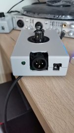
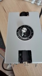
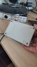
I have an update: I designed a front and back panel PCB that fits the Hammond case. Here is a picture of my own unit with the new panels:

I'll upload the design files to Github soon. This is the first attempt, so as you can see the hole around the XLR is about 1mm too large, otherwise it's a pretty nice fit. Since the PCB is copper, it makes a shielded box all around.
Since I ordered 5 of these PCB's I have 4 extra that I'll send for free to those who can prove with a picture that they have already built it in a Hammond case. Jsenderatx, you are probably on that list?
I have an update: I designed a front and back panel PCB that fits the Hammond case. Here is a picture of my own unit with the new panels:
I'll upload the design files to Github soon. This is the first attempt, so as you can see the hole around the XLR is about 1mm too large, otherwise it's a pretty nice fit. Since the PCB is copper, it makes a shielded box all around.
Since I ordered 5 of these PCB's I have 4 extra that I'll send for free to those who can prove with a picture that they have already built it in a Hammond case. Jsenderatx, you are probably on that list?
Yes indeedy! Here are my three bad-boys in their cases.Jsenderatx, you are probably on that list?
Very kind of you! I'll use one set of plates as a guide to drill the other two.
I suppose I will send a DM with my mailing address, cheers!
I'm also interested in this build. Do you have a link for the PSU you use ?
Really appreciate the new enclosure and the updated BOM (way better now).
Really appreciate the new enclosure and the updated BOM (way better now).
Hi, glad you like the update.
I happened to have a 48V AC/DC PSU in my PSU box, so I've just used that one.
If I were to buy one, the MeanWell SGA12E48 (for Europe) or SGA12U48 (for US) looks pretty good. Not grounded, so that it doesn't introduce ground-loops, and the ripple for 48V version is only 100mV which is pretty good for such a small and cheap PSU. 12W is enough to power several channels, and it's from a reputable manufacturer with all the safety and EMC certificates in order.
Wow! That was fast! Just two weeks since I posted the frontpanel gerbers, and here they are already being used!
Which enclosure is this? It has the same dimensions as the Hammond case, but the ridges tells me it's something else but with similar dimensions?
Which enclosure is this? It has the same dimensions as the Hammond case, but the ridges tells me it's something else but with similar dimensions?
It is sold on Taobao. com in China.Wow! That was fast! Just two weeks since I posted the frontpanel gerbers, and here they are already being used!
Which enclosure is this? It has the same dimensions as the Hammond case, but the ridges tells me it's something else but with similar dimensions?
RMB 20, express fee 7.
Size: 78x43x120
Last edited:
- Home
- Design & Build
- Equipment & Tools
- ThatMicPre - an open-source mic preamp