Wow! That is excellent work! The craftsmanship with the heat shrink wrapped connectors, the bracket for the DC plug, not to mention the faceplate! Really nice looking! I also like that you used what you already had, it is in keeping with the spirit of the project, to use as many common parts as possible that people probably already have in their drawer.
Thank you so much for sharing the result, it encourages me to do more open source hardware projects in the future to see what people make of it. Thank you!
OJG
Thank you so much for sharing the result, it encourages me to do more open source hardware projects in the future to see what people make of it. Thank you!
OJG

I just ordered the BOM and the PCBs from oshpark -- looking forward to trying this out!
I have a question about the D14 LED. In the schematic, the (+) of D14 connects to R28, but on the PCB, the square (+) solder pad for D14 is running to D17/C18. Is the component simply backwards in PCB design? Should I install the (+) lead for D14 into the circle solder pad rather than the usual square for +?
Also in the image of the populated PCB, it looks like one of the D14 legs in running somewhere that's not pictured. Where is the unseen leg for D14 going?
Hi! Glad to hear that you want to build one!
It seems that I have chosen a footprint where the ring is cathode and the square is anode. It's the same for D10 and D14.
The picture is of the v1.0 board which I modified with a jumper wire in this area to be the same as v1.1.
It seems that I have chosen a footprint where the ring is cathode and the square is anode. It's the same for D10 and D14.
The picture is of the v1.0 board which I modified with a jumper wire in this area to be the same as v1.1.
I still have some time to wait on the PCBs to arrive, but another question in the meantime:
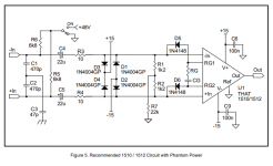
I've remembered that I have an extra THAT1512 chip sitting around unused in addition to the 1510 that I ordered with this BOM. I am thinking that it could be interesting to build and compare two versions, one with the 1510 and another with the 1512 since I'll have both. I see that in the THAT1510/1512 datasheet, they have an identical recommended circuit for both chips (shown below) -- so I'm wondering if it's okay to use the same components for both 1510 and 1512 versions of this build? Would the pot resistors also be the same?
I've remembered that I have an extra THAT1512 chip sitting around unused in addition to the 1510 that I ordered with this BOM. I am thinking that it could be interesting to build and compare two versions, one with the 1510 and another with the 1512 since I'll have both. I see that in the THAT1510/1512 datasheet, they have an identical recommended circuit for both chips (shown below) -- so I'm wondering if it's okay to use the same components for both 1510 and 1512 versions of this build? Would the pot resistors also be the same?
Attachments
The THAT1512 should work just fine. If you use the same resistor values for the gains, the gains will just be 6dB lower for all settings. I.e. the range will be -6, 4, 9, 14, ..., 54.
There is a Matlab/Octave script in the Github root folder that you can use to calculate gain resistor values for both the 1510 and 1512 and other similar parts for any gain range you want.
There is a Matlab/Octave script in the Github root folder that you can use to calculate gain resistor values for both the 1510 and 1512 and other similar parts for any gain range you want.
My PCBs arrived last night and I couldn't resist diving right in. A picture of my populated board is below (I had some larger footprint .01 film caps that I used, too fat to fit at C15/C17, so they're installed on the underside).
Unfortunately...I'm not getting any signal out of it.
Do you have a recommended power supply? I'm using a Mean Well 48v .84A switching PSU (part# GSM40A48-P1J) which I already had -- should that power supply be compatible?
My D14 LED does not light up (it flashes briefly when I switch on phantom, but then immediately fades out again). The D10 LED does light up when phantom is on. There is a blip in the signal when you engage phantom, but other than that, I'm not getting any signal.
I've double-checked my resistors and polarized component orientation and everything seems in order. I do have 2 more boards and most of the BOM for a couple more builds, so I can go for a second and cross my fingers, but any thoughts about my PSU or D14 behavior or other ideas would be appreciated.
Hi! Your assembly looks fine, I know the feeling when new PCBs arrive 🙂
Your power supply is probably fine.
Do you have a multi-meter? Any cheap one will do, just to check the DC voltages on the board.
The information that D14 turns on briefly when you switch phantom on tells me there might be some problem with Q2 and/or the components around it. Could you measure the voltages from collector, base and emitter to ground of Q2? There should be approx 48V on collector, 36V on base and 35V on emitter.
(could C15/C17 fit on top of the board if you moved R27/R30 to the bottom?)
OJG
Great, thank you for the quick aid!
I'm testing a steady 47.8v collector, 46.5v base, and 0.5v emitter. So you nailed it.
I was also suspecting Q2 simply because (a detail I left out) the first time I power up the unit I had C11 installed backwards 😒 so I thought that could have hurt something in that area and Q2 seemed most likely.
Should I simply swap out Q2? Easy enough. Or what other parts may also have been hurt?
Moving R27/30 to the bottom is a swell idea. I'll do that for board#2.
It's always a bummer to finish and not have the unit spinning like a top, but it was a very nice build experience. Love the design.
Thanks for the tips, let me know what you think, cheers.
I would first touch up the solder joints on Q2 just to make sure there are no cold solder joints.
Although with 46.5V on the base, it could seem that D15/D16 isn't working right either, (or that D19 is the wrong way around, but from the picture it looks ok). I would remove Q2 and then measure the voltage across D15+D16, it should be 36V then.
Although with 46.5V on the base, it could seem that D15/D16 isn't working right either, (or that D19 is the wrong way around, but from the picture it looks ok). I would remove Q2 and then measure the voltage across D15+D16, it should be 36V then.
Yep D19 is oriented the correct way according to the printing on the board, and indeed with Q2 removed, I measure 36.3v across D15/16.
I decided to just go for it and give it a try with a fresh Q2 transistor, and presto it's working!
I haven't spent much time with it yet, but sure sounds like some nice clean gain.
Thanks again for the troubleshooting tips! I'm still planning on making an additional build to compare using 1510 and 1512, so I'll let you know if that results in anything interesting. Cheers!
I haven't spent much time with it yet, but sure sounds like some nice clean gain.
Thanks again for the troubleshooting tips! I'm still planning on making an additional build to compare using 1510 and 1512, so I'll let you know if that results in anything interesting. Cheers!
All three of my builds are now finished and sounding great! Unbelievably quiet. Maybe it's just because I've mostly been using tube pres for many years now, but wow, these are QUIET. Very crisp but still pleasant sounding as well.
I've always been a suckers for blind A/B comparisons and am still looking forward to doing some more in depth comparisons of these units. The top two in the attached image are using mostly the BOM, but one with the THAT1510 and one with 1512. The bottom one is using Dale RN resistors and Nichicon UFG caps. I also installed an 8-pin socket at U1 and also got SSM2019 and INA217 chips to drop in to be able to compare these 4 different chips within the exact same circuit. Haven't done much yet, but can confirm that all four of these amp chips work and sound good dropped in at U1.
As you can see I also got one in the Hammond 1455K120 chassis (but haven't yet drilled a hole in the top panel for the pot to stick out. I found that the taller PW(M) caps from the BOM were making contact with the side rail of the chassis. The UFG caps in my third build are very slightly shorter and fit inside the chassis without making contact with the body. So I would recommend slightly shorter 220u caps if using this case.
Thanks yet again for the awesome project! I'll let everyone know if I end up picking a clear favorite out of the four different preamp chips.
Hi, ojg!Hi! Your assembly looks fine, I know the feeling when new PCBs arrive 🙂
Your power supply is probably fine.
Do you have a multi-meter? Any cheap one will do, just to check the DC voltages on the board.
The information that D14 turns on briefly when you switch phantom on tells me there might be some problem with Q2 and/or the components around it. Could you measure the voltages from collector, base and emitter to ground of Q2? There should be approx 48V on collector, 36V on base and 35V on emitter.
(could C15/C17 fit on top of the board if you moved R27/R30 to the bottom?)
OJG
I made a thatmicpre according to your design.
But it doesn't work properly.
I worked on it for a few days and still haven't solved it.
To make matters worse, when I was measuring the voltage of the chip just now, I short-circuited the two pins of the chip, the chip was broken, and the circuit was also short-circuited.
So I decided to build a new one, and start with the power supply part.
I have done the part of power supplying for chip.
After plugging in, the 7th-pin position of the chip has a voltage about 35 volts, and the led light was on.
There's nothing wrong with that part, right?
According to my broken one, after the phantom switch is turned on, pins 2nd and 3th of J2 have around 48 volts.
And the phantom power LED lighted up.
This was also correct, right?
Then I don't know what is wrong.
I suspect there is something wrong with my chips.
Can you tell me what are the voltages of the 8 pins at the chip location when the that1510 is not mounted?
I want to make sure that my board provides the correct working environment for the chip.
Thank you!
I suspect there is something wrong with my chips.
Hey I can't help with your voltage questions, but maybe with your THAT1510 concern. When I built my preamps, I tried multiple different preamp chips, including a fake THAT1510 that I ordered from EBay. The THAT1510 from EBay did not work. I suspect you may also have a fake THAT1510 chip because it looks similar to the fake one I have.
You can see in the included image below of a real THAT chip, there is a divot on the left edge, AND a little circle shaped depression on the chip below the "T" logo. Your chip looks like the one I got that did not work. The real THAT chips that I ordered from Mouser were legit and work, but I would avoid getting these on EBay or Alibaba or other independent seller because there are clearly some counterfeit THAT chips out there.
No guarantees this is your issue of course, but seems likely, especially if you didn't get the chip from an official THAT retailer.
thank you!Hey I can't help with your voltage questions, but maybe with your THAT1510 concern. When I built my preamps, I tried multiple different preamp chips, including a fake THAT1510 that I ordered from EBay. The THAT1510 from EBay did not work. I suspect you may also have a fake THAT1510 chip because it looks similar to the fake one I have.
You can see in the included image below of a real THAT chip, there is a divot on the left edge, AND a little circle shaped depression on the chip below the "T" logo. Your chip looks like the one I got that did not work. The real THAT chips that I ordered from Mouser were legit and work, but I would avoid getting these on EBay or Alibaba or other independent seller because there are clearly some counterfeit THAT chips out there.
No guarantees this is your issue of course, but seems likely, especially if you didn't get the chip from an official THAT retailer.
View attachment 1085423
I will order some 1510 chips from mouser and check if it works
Last edited:
Can you tell me what are the voltages of the 8 pins at the chip location when the that1510 is not mounted?
Without the THAT1510 mounted, there should be 35V on pin 7 and 18V on pins 2, 3 and 5. The rest should measure 0V.
Good luck with your build! And yes, I highly recommend buying the IC from a proper distributor. When you put so much time into a build, potentially saving a few bucks by ordering parts from unknown sources isn't worth it.
OJG
Thank you,OJG!Without the THAT1510 mounted, there should be 35V on pin 7 and 18V on pins 2, 3 and 5. The rest should measure 0V.
Good luck with your build! And yes, I highly recommend buying the IC from a proper distributor. When you put so much time into a build, potentially saving a few bucks by ordering parts from unknown sources isn't worth it.
OJG
I built my second thatmicpre today without sw3 (sw_rotary12), and measured the voltages of each pins without that1510.
When phantom power is on, the voltages are as follows.
2nd pin - 18V
3th pin - 18V
5th pin - 18V
6th pin - 0V
7th pin - 35.6V
But when phantom power is on, the voltages of 2nd and 3th pin are about 14 to 16V.
I think it shouldn't be a problem, right?
Then I'll just wait for the new chips to arrive. It will take about two weeks to get them.
- Home
- Design & Build
- Equipment & Tools
- ThatMicPre - an open-source mic preamp