. For the distortion, yes, but it is not in just strict relation with the driver alone. Distortion will change with the box too.
Exactly. When I was referring to "subwoofer" measurement, I wasn't referring to the driver, but the driver/box combination.
We can agree on that, but keep in mind that some are just happy that their driver survived, and that's how power is counted. ��
I seriously do not know exactly how much they can take before severe power compression steps in, or thermal failure occurs (mechanical failure is rare and usually a secondary effect to temperature) but I have heard of several successful long term user cases (multiple seasons on tour) with power estimations around and in some cases above 1kw/box, without any detectable issues, this is of course driver dependent, in these cases it has almost exclusively been good quality drivers of well known brands with appropriate power ratings.
Exactly I totally agree, you can not just expect that the driver specs say 1000w nominal and 2000w continuous power, So let's give it 2000w because the driver specs say so. As Brian says, It really depends on driver/cabinet combination. So doing a HR sim with driver and getting it to xmax rating (which in HR is conservative) can be a good save starting point.
Measuring the subwoofer for nonlinear distortion using sine waves at certain frequencies is a good method to determine the performance capabilities of the subwoofer using ANSI/CTA-2010-A (or known as CEA-2010) test. However for me (still learning) are quite difficult to interpret the FFT and distortion percentage of the measurements. It also takes some time measure and do it right.
With some cabinets you can hear the sound change when adding more voltage for example front loaded designs, with horns/flh/th/compound etc it's very hard to do by ear, if you hear distortion it's most of the time already too late.
just reassure me guys, how far can I go with the RCF LF15N401 in the THAM 15 before "burning it" ?
RCF LF15N401 - 15" Woofer
RCF LF15N401 - 15" Woofer
I think you can safely do 700w MAX SPL with a 35hz/24db BW highpass. this leaves some room for peaks.
I logically presume the amp has twice the rating of the subwoofer.
I logically presume the amp has twice the rating of the subwoofer.
Last edited:
A RCF LF15N401 will take 1500 watts of short uncompressed non-clipped peaks in a THAM15, but a heavily compressed signal through a 800 watt amp that is driven into clipping will kill the driver quite fast.
It is always better to have some headroom and use the gear with some common sense, then use a comparably weak amp constantly to its limits.
It is always better to have some headroom and use the gear with some common sense, then use a comparably weak amp constantly to its limits.
If you are going to push all the power on the driver, I say build more cabinets. Doing 1200w into it will not last hours and it will go into power compression in some time or worse.
Exactly I totally agree, you can not just expect that the driver specs say 1000w nominal and 2000w continuous power, So let's give it 2000w because the driver specs say so.
When I say 1500 watts or 1200 watts I assume people know that music is in its nature a highly dynamic medium. With a 20 - 30 dB dynamic range the 1500 watt peak means that the average power level is 15 to 1,5 watts. I am certain the RCF LF15N401 survives short peaks of 1500 watts with prolonged periods of 1,5 - 15 watts in between.
I assume nobody here is stupid enough to run a 40 Hz 2 kw sinewave or squarewave through a 15 inch driver for a few hours.
If you start compressing the signal hard and push the amps to just below clipping for long periods then it is the user that is faulty and should be replaced.
Well, to my horror, people expect to do exactly that, and then they wonder why it burned. Then they have the nerve to blame the manufacturer for poor performance and false advertising... DOH.
If you start compressing the signal hard and push the amps to just below clipping for long periods then it is the user that is faulty and should be replaced.
LMAO - word!
@circloman, We all know the HR xmax 'prediction' is a bit off.
Interestingly enough, that hasn't been my experience.
Let me clarify - as mentioned before, as part of my testing, I check to see what voltage level is required for the subwoofer system to hit 10% THD in its passband. I've found, albeit for the few that I've tested so far, that this drive voltage usually isn't far off from what Hornresp predicts would be the drive voltage required to push the driver's cone past Xmax in the sim of the subwoofer.
Which somewhat makes since if you look at the Hornresp output of the sims (frequency response, impedance curve, excursion curve, etc.) as basically different "views" of the same alignment. If measurements of the built subwoofer show that one of those outputs is noticeably off, then either the Hornresp simulation process is wrong, or the build does not match what was sim'd.
Having said that, we know that Hornresp does not take into consideration a few things, such as:
1. Any box losses (which shouldn't have a big impact on driver excursion, if kept low = well-built box)
2. Driver non-linear excursion (which for a good driver should start to be noticeable near and beyond Xmax anyway)
3. Dynamic compression effects (e.g. vent sizes that are too small)
The big one for me there is (2). When I see discussions about "driver excursion being less than predicted by Hornresp", I wonder if that's an observation that's being done when the driver's excursion is actually beyond its linear range of operation, which should show up in linearity or THD testing. I'd love to see more THD and linearity tests (they're not difficult to do), but alas you don't see much of those.
And here at 1200w:
What does the diaphragm displacement comparison look like at low frequencies, assuming a 200 deg C voice coil temperature?
A RCF LF15N401 will take 1500 watts of short uncompressed non-clipped peaks in a THAM15, but a heavily compressed signal through a 800 watt amp that is driven into clipping will kill the driver quite fast.
What do you mean by an "heavy compressed signal" ? Im having an active crossover/DSP sending signals to my CLass D Amp that I pay attention to not push the amp signal close the "clipping area"
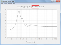
@David what low frequencies you are thinking about? Since I assumed the power compression setting with input of 200c is for the whole graphical representation in HR.
What i see in the graph (tham15 with 15NBX100-8 @800w (80v) as example:

What i do notice, is the power compression is more in relation to negative xmax. I expected power compression would be more severe on high xmax.
What i see in the graph (tham15 with 15NBX100-8 @800w (80v) as example:
What i do notice, is the power compression is more in relation to negative xmax. I expected power compression would be more severe on high xmax.
Last edited:
Nope. Cone excursion is not directly related to real power spent on the coil as heat. But I would also expect we would see more dips at impedance minimums.
Originally Posted by Circlomanen
If you start compressing the signal hard and push the amps to just below clipping for long periods then it is the user that is faulty and should be replaced.
LMAO!
Last edited:
Hi USRFobiwan,
Thanks for posting the comparison.
I was just wondering what effect a voice coil temperature of 200 deg C would have on the diaphragm displacement of the system in question below about 40 Hz. Not much it would seem, at least not until you get below 20 Hz. Unfortunately the quoted driver Xmax of 10 mm is exceeded below about 40 Hz with or without the Power Compression tool being used.
You assumed correctly 🙂. The voice coil temperature is included in each chart title when the Power Compression tool is used, to indicate that this is indeed the case.
Kind regards,
David
@David what low frequencies you are thinking about?
Thanks for posting the comparison.
I was just wondering what effect a voice coil temperature of 200 deg C would have on the diaphragm displacement of the system in question below about 40 Hz. Not much it would seem, at least not until you get below 20 Hz. Unfortunately the quoted driver Xmax of 10 mm is exceeded below about 40 Hz with or without the Power Compression tool being used.
Since I assumed the power compression setting with input of 200c is for the whole graphical representation in HR.
You assumed correctly 🙂. The voice coil temperature is included in each chart title when the Power Compression tool is used, to indicate that this is indeed the case.
Kind regards,
David
Attachments
I did a quick measurement of one of my THAMs. Not too close to the simu, but looking and sounding good. For more information see here.
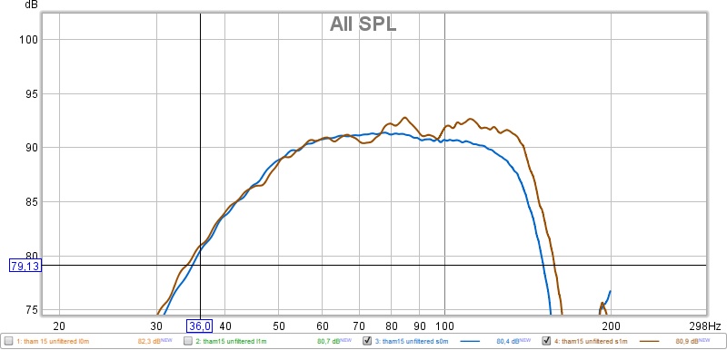
Looks like the -3dB point is around 50 Hz for the raw response.
Did you take an impedance curve as well? That will also show how close (or not) the response of the built THAM15 is to the sim'd response.
Pro audio woofer boxes that have an F3 around 50 Hz are interesting, in that they're fine for most purposes. However, compare them to a 40 Hz (or lower) capable box, and most people would prefer the box that goes lower (based on my albeit unofficial polling 🙂 ). My POC6 build has a similar cutoff frequency, so it was fairly easy to do the comparison between it and my POC3, which can get down to 40 Hz.
- Home
- Loudspeakers
- Subwoofers
- THAM15 - a compact 15" tapped horn