Yes, using a driver with more displacement, and the power handling to deliver the displacement could give ~+4dBSPL peak output, maybe less than +3dB when power compression losses from voice coil heating are taken into account. The 18SW115 is rated 1700watts (AES), 18TBX100 1000watts, less than +3dB power handling difference.
Ideally, each doubling of mutually coupled cabinets and power results in +6dB output, +3dB efficiency from doubling the cone area and cabinet volume, +3dB from doubling the power.
Say one 18TBX100 does 126 dB, two will do 132dB, four 138dB.
One 18SW115 does +4dB, 130dB, two will do 136dB, four 142dB.
The next +6dB requires another trailer 😉

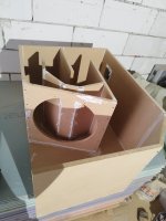
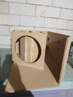
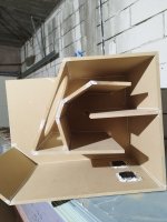
For the cone correction would it be best for the 100mm section in the centre to be parralel with the baffle or at the same 4° angle as the rest of the horn? Also as mentioned in a few posts earlier on, the 36° angle is too steep and causes an early expansion, playing around, 24° seems to provide a more even expansion to the first fold, I'm still plotting out a flattened horn and can then play around with the parameters a bit more.

The initial expansion is closer to 17° when the cone correction line is added` (approx 19 ° to the baffle dependent on Driver cone profile). Of course this is still bigger than the 2.7° of the S2 -S3 section. Probably due to adapting from the original TH18 layout - Either the compression could be reduced or the entire S2 to S3 section tapered more. But that is the complication of applying this geometry - The speaker becomes driver specific to a degree and looses its one size suits many drivers layout that has seemed to be fairly sucessful!
I'm not agree with that, different angle than parallel with cone is not correction.
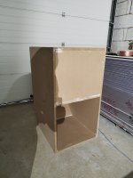
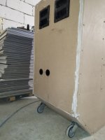
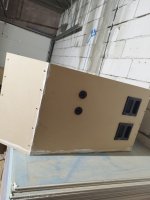
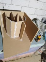
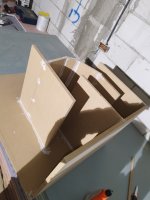
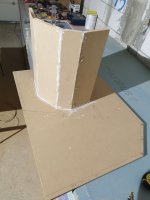
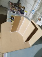
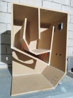
I built two boxes th118 in that way and i listened, good feedback and deep bass.
Not are finished yet, last steps to cover screws, edges and painting.
Many thanks and great people on this thread ⭐⭐⭐⭐
I built two boxes th118 in that way and i listened, good feedback and deep bass.
Not are finished yet, last steps to cover screws, edges and painting.
Many thanks and great people on this thread ⭐⭐⭐⭐
Attachments
-
 IMG_20240315_095856.jpg266.7 KB · Views: 191
 -
 IMG_20240315_132139.jpg364.2 KB · Views: 193
 -
 IMG_20240315_132146.jpg288.9 KB · Views: 181
 -
 IMG_20240331_140533.jpg258.6 KB · Views: 177
 -
 IMG_20240316_110408.jpg278.3 KB · Views: 192
 -
 IMG_20240316_113535.jpg257.8 KB · Views: 194
 -
 IMG_20240316_110416.jpg272.1 KB · Views: 194
 -
 IMG_20240314_182355.jpg341.1 KB · Views: 182
 -
 IMG_20240315_093913.jpg290.6 KB · Views: 180
 -
 IMG_20240315_093905.jpg310.2 KB · Views: 180
 -
 IMG_20240314_175518.jpg280.2 KB · Views: 169
 -
 IMG_20240314_161553.jpg328.5 KB · Views: 168
 -
 IMG_20240314_180821.jpg306 KB · Views: 168
 -
 IMG_20240314_175513.jpg397.9 KB · Views: 159
 -
 IMG_20240314_175506.jpg326.7 KB · Views: 157
 -
 IMG_20240314_163819.jpg333.8 KB · Views: 192
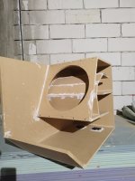
Remember that the cone is, well, a cone. Consider how the CSA changes as you move from the edge of the cone to the center. It's very different to how the CSA will change between two non-parallel flat panels. As a result, if adjusting a panel to compensate for the cone, its angle will definitely not be the same as the cone's angle.
First sound waves where hit the panel and create main pressure, like intake after exhaust. Second corner with second pressure, third corner create third pressure with 4 corners pushing out that pressure one by one, this is my opinion and is very clear for me if i did a mistake i'm here to listen.
Attachments
The angles though are based on the average CSA from Martins calculations (post #2,963) not the actual angle of the cone.Remember that the cone is, well, a cone. Consider how the CSA changes as you move from the edge of the cone to the center. It's very different to how the CSA will change between two non-parallel flat panels. As a result, if adjusting a panel to compensate for the cone, its angle will definitely not be the same as the cone's angle.
Last edited:
But none of the sound waves in the bandwidth have that short of a 1/4 wavelength ? So how are you going to create these ‘pressure/Velocity’ points at those fold/direction changes?First sound waves where hit the panel and create main pressure, like intake after exhaust. Second corner with second pressure, third corner create third pressure with 4 corners pushing out that pressure one by one, this is my opinion and is very clear for me if i did a mistake i'm here to listen.
Hi, I'm planning on building four TH18s, I see there are various pictures with or without corner deflectors, and various pictures with the modified panels for cone correction, is there a final drawing incorporating the latest mods, many thanks.
Speaking of cone correction , what is the deal with it, you have to? Cause I see people building cabinets without it and are happy.
Is just for high power drivers?
Or is like having leather seats, you can still drive from point A to B with a clothed seats vehicle
Is just for high power drivers?
Or is like having leather seats, you can still drive from point A to B with a clothed seats vehicle
How does it sound at 200? The low end is fine, I can EQ and it's NOT level restricted. 4 12"s per side in this space as direct radiators are plenty of output, but a nice clean TH is pretty compelling and everything above 150-200 is already horn loaded. A pair of these per side would be a solid 30dB of headroom I'd never, ever touch.
Well, original project doesn't have deflectors with one exception for handling. Where the wave sound hit the corner creating deep bass. ++corners will be deep and deep + delay and directive decrease in front but help for a quality target of sound. Cheers
Attachments
Also considering for ease of building making the
Still playing around with models and considering if the ease of that 90 angle will affect things?

You won't lose much if any low-frequency performance if you build it like the example below, and it should be a slightly easier build, and I suspect a bit safer for the driver as well.
View attachment 1259621
Still playing around with models and considering if the ease of that 90 angle will affect things?
That drawing looks a lot different that what you built, the cone correction is right up to the baffle and then folded back on much steeper angles - does that just apply a lot great compression on the driver?Well, original project doesn't have deflectors with one exception for handling. Where the wave sound hit the corner creating deep bass. ++corners will be deep and deep + delay and directive decrease in front but help for a quality target of sound. Cheers
Do not use corner reflectors unless you add volume to the enclosure to compensate for the loss of air space.
Read JBell's SS15 thread about them.
They take away volume from the original model and lower SPL in ground plane measurements.
Read JBell's SS15 thread about them.
They take away volume from the original model and lower SPL in ground plane measurements.
there is a safe area and it doesn't harm the driver on a wide range of models, it doesn't matter what you load in this case. if you have the measurements in hand, you can do the different model cone correction and get closer to it and make the compression higher, gaining extra power (driver stress)That drawing looks a lot different that what you built, the cone correction is right up to the baffle and then folded back on much steeper angles - does that just apply a lot great compression on the driver?
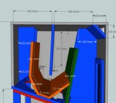
Some more playing around with the model and finally got the parameters into hornresp.
S2 is based on a compression ration of 3:1 - presumably that's not too much for a B&C 18SW115-4?


S2 is based on a compression ration of 3:1 - presumably that's not too much for a B&C 18SW115-4?
Looks good. But why sim in 0.5 PI - are you really going to put this cabinet in a corner! Or just looking to build 4?
- Home
- Loudspeakers
- Subwoofers
- TH-18 Flat to 35hz! (Xoc1's design)