@Andy
Some time to spare...
You might want to recheck that sim. You've got S1=S2, and Conical rather than Parabolic expansion.
I used the TH18 sim from here - The Subwoofer DIY Page v1.1 - Projects : DIYAUdio Projects - The TH18
... which in turn I extracted from a post much earlier in this thread.
Hi Brian,
should have taken more time - I quickly took my TH18 sim lying in my folder, entered loong time ago and when andy wrote "version 1", I thought this is the one. I guess this was an earlier version from here:
http://www.diyaudio.com/forums/subwoofers/178029-c-e-x-pa-flat-30-ft30-pa-th-awesomeness.html
Thanx for pointing me to the version which seems to be closer to Andys build.
Hi Brian,
Thank you very much for all the comments and the interpretation of the results of the measurement.
1. It is going to be difficult to find out if there are any leaks. I have made sure the the cut in the baffle is exactly as per B&C tecnical drawing so that the the driver sits on the gasket material and is evenly fastened with bolts washers and nuts. What else can you do in that department?
Could it be due to the added cone correction?
I have a steel grill with 48% airflow and my a/b testing did not show any difference in output. Could that make a difference that I didn't notice?
I also wondered if the grill could have influence at higher output, which my test is not accounting for.
I have internal bracing but no bracing in the mouth except for the grill. Could that make a difference? I have heard people saying that the sub could 'walk' on high power, but I never experienced that.
For items 2 and 3 I don' know what to say, except that the measurement setup could be with a lower Res, which might change the result a bit.
I have added a FR in text format here and I would appreciate it a lot if you could comment on that also.
Regards, Andy
Attachments
Hi Brian,Great, thanks for this Andy.
As Dan mentioned, do you keep the measurement files? I'd like to see them, particularly to see how the measurements compared to the simulated results.
Out of interest, I think it would be great to see what the FR looks like without the filtering.
On the impedance measurement, for best accuracy (e.g. to compare to the HornResp sim), based on my own tests the TH should be on the ground and at least one mouth's diameter away from any wall or other surface that can "load" the mouth and shift Fb. From the graph you gave, it looks like there's some sort of resonance occurring at 35 Hz, 67? Hz and 83? Hz, which could be caused by room modes (seeing that the measurement was done with the TH in a corner), though the usual culprit is panel flex.
FR in text format on the same cab with no HP filter here.
Thank you for the advice on impedance measurements. I will keep that in mind next time.
Best, Andy
I'll take this in two parts... ")
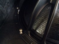
It's not that difficult. You'll need to take the FR test a low lower though, like starting around 10 Hz, 20 Hz minimum. If there's a leak, it will show up as a noticeable "blip" in the FR curve before reaching the passband of the TH. I've included an example FR that shows the impact of a pretty bad leak around the driver.
The B&C cutout spec is in reference to the driver being mounted through the baffle, not on top of it. Yeah, I made the same "mistake" too, LOL. It's not bad if you're capable of cutting out perfect circles and the driver is mounted dead-center. Otherwise I believe that there's only 0.5mm to play with, which provides a good opportunity for the gasket to slightly overlap the baffle, particularly when compressed down on it, and one of the cutouts in the gasket for the screws being exposed and causing a leak. Making the driver cutout a few mm smaller in diameter is a great way to avoid this issue entirely. And it will make no difference to the TH's output otherwise.
No. Cone correction only has adverse effects if there's too much of it. Your build does not seem to suffer from that.
It's possible. The only way to make sure is to repeat the impedance test, this time with the grill off. Any difference in the impedance curve will be reflected in a difference in the frequency response, and it's usually a lot easier to measure the impedance curve.
See my next post
It is going to be difficult to find out if there are any leaks.
It's not that difficult. You'll need to take the FR test a low lower though, like starting around 10 Hz, 20 Hz minimum. If there's a leak, it will show up as a noticeable "blip" in the FR curve before reaching the passband of the TH. I've included an example FR that shows the impact of a pretty bad leak around the driver.
I have made sure the the cut in the baffle is exactly as per B&C tecnical drawing so that the the driver sits on the gasket material and is evenly fastened with bolts washers and nuts.
The B&C cutout spec is in reference to the driver being mounted through the baffle, not on top of it. Yeah, I made the same "mistake" too, LOL. It's not bad if you're capable of cutting out perfect circles and the driver is mounted dead-center. Otherwise I believe that there's only 0.5mm to play with, which provides a good opportunity for the gasket to slightly overlap the baffle, particularly when compressed down on it, and one of the cutouts in the gasket for the screws being exposed and causing a leak. Making the driver cutout a few mm smaller in diameter is a great way to avoid this issue entirely. And it will make no difference to the TH's output otherwise.
Could it be due to the added cone correction?
No. Cone correction only has adverse effects if there's too much of it. Your build does not seem to suffer from that.
I have a steel grill with 48% airflow and my a/b testing did not show any difference in output. Could that make a difference that I didn't notice?
It's possible. The only way to make sure is to repeat the impedance test, this time with the grill off. Any difference in the impedance curve will be reflected in a difference in the frequency response, and it's usually a lot easier to measure the impedance curve
.I have added a FR in text format here and I would appreciate it a lot if you could comment on that also.
See my next post
Attachments
I have added a FR in text format here and I would appreciate it a lot if you could comment on that also.
Here ya go. I'd say it actually looks pretty good when compared to the sim, though for a better comparison it would best to use the raw FR rather than the filtered FR. The passband-shape is a good match (with a dB or two loss at the lower end of the passband).
Extending the FR test down to at least 20 Hz if not lower and recording the raw results (no filtering) would help to determine if that loss around 40~50 Hz is due to leakage or just normal losses, and I expect that it's likely the latter.
Attachments
That's no text file...
I'll throw my modified throat version of the TH18 into the fray
REW File


I'll leave these links active for a month or so.
REW File
An externally hosted image should be here but it was not working when we last tested it.
I'll leave these links active for a month or so.
Last edited:
I'll throw my modified throat version of the TH18 into the fray
How do the measured results compare to the sim?
How do the measured results compare to the sim?
Like so:
An externally hosted image should be here but it was not working when we last tested it.
Not bad..
That dip below 30 Hz looks like an active filter effect.
The smoother passband and the loss around 80 Hz could be due to slightly too much cone compensation, based on the results of some tests I did with POC3.
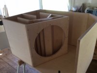
The layout looks very similar to my POC4.1 (I don't include the corner reflectors, as I don't believe that they're important in a bass-horn, and can in fact push UP Fb). I'm still fine-tuning the layout spreadsheet for it - it's a true 32 Hz horn that has the same front dimensions as the TH18, but its depth is extended from 28" to 32". That extra 3 Hz is expensive....
It's interesting that the passband is mostly below 100 dB though. Is that a 2.83V sim or a 1W sim?
That dip below 30 Hz looks like an active filter effect.
The smoother passband and the loss around 80 Hz could be due to slightly too much cone compensation, based on the results of some tests I did with POC3.
The layout looks very similar to my POC4.1 (I don't include the corner reflectors, as I don't believe that they're important in a bass-horn, and can in fact push UP Fb). I'm still fine-tuning the layout spreadsheet for it - it's a true 32 Hz horn that has the same front dimensions as the TH18, but its depth is extended from 28" to 32". That extra 3 Hz is expensive....
It's interesting that the passband is mostly below 100 dB though. Is that a 2.83V sim or a 1W sim?
Attachments
TH18_FR_no_HP_txt
I see the file is huge, lucky me that it wasn't something nasty :0)
Important to add:
The measurements, being the one with HP 30/48 BW and without HP was done separately with different methods of calibrating the relative db scale.
So you cannot make a 1:1 compare between the two based on individual db readings.
The link to the FR with no HP filter in text format should be ok now.
and here is the FR with HP filter 30/48 BW.
/ Andy
Hi Brian,
Appreciate you help a lot.
I must say that I am a bit lost on how make the necessary corrections, should the cabs have a leak by the driver but let's see.
I will make a raw outdoor impedance and FR measurement extending the measurment low to 20hz, maybe later today or during the weekend depending on the weather.
I will also make impedance and FR measurments with and without the grill.
Did I miss something?
Cheers, Andy
Hmm... that new measurement looks like it was taken under entirely different conditions (maybe the TH was up against a wall or something?). It also looks like there was still some low-pass filtering involved.
See the comparison with the HornResp model attached.
See the comparison with the HornResp model attached.
Attachments
I must say that I am a bit lost on how make the necessary corrections, should the cabs have a leak by the driver but let's see.
I wouldn't worry about it yet. Chances are that there is no leak at all, and what you're seeing is simply the result of box losses.
In the VERY off chance that there IS a leak, a suitably wide and firm gasket that shrinks the cutout's effective diameter to about 418 mm should fix it nicely. See this thread for ideas: - http://www.diyaudio.com/forums/subwoofers/275969-when-things-dont-go-quite-planned.html
@ Brian:
There is more than one year between the measurements. The same equipment was used except for the amp. Both where conducted outdoor but I am sure there are differences in the position/direction of the sub and mic.
But never mind that because I made brand new REW measurements this weekend that should be consistent as everything was done with great attention to not make any changes to the setup except those that we want to make changes to and compare - in this case the influence of a grill with aprox. 50% airflow.
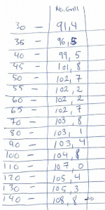
I have also made 'static'/separate frequency SPL(dBC) measurements to have 2.83v@1meter SPL readings that I think I can rely on. They are actually not that far off the calibrated readings that I am making within REW. Please excuse the handwriting
SPL(dBC) separate frequency measurment
Frequency repsonse and SPL with and without Grill:
Comparing FR from 10hz to 250Hz and SPL on the same sub with and without a grill made in 2mm aluminium with approximately 50% airflow firmly attached to a frame (1.5cm x 1.5cm) inside the mouth.
FR with grill
FR without grill
Impedance with and without grill:
IMP with grill
IMP without grill
Here are the REW files:
FR with grill
FR without grill
IMP with and without grill
/ Best Andy
There is more than one year between the measurements. The same equipment was used except for the amp. Both where conducted outdoor but I am sure there are differences in the position/direction of the sub and mic.
But never mind that because I made brand new REW measurements this weekend that should be consistent as everything was done with great attention to not make any changes to the setup except those that we want to make changes to and compare - in this case the influence of a grill with aprox. 50% airflow.
I have also made 'static'/separate frequency SPL(dBC) measurements to have 2.83v@1meter SPL readings that I think I can rely on. They are actually not that far off the calibrated readings that I am making within REW. Please excuse the handwriting
SPL(dBC) separate frequency measurment
Frequency repsonse and SPL with and without Grill:
Comparing FR from 10hz to 250Hz and SPL on the same sub with and without a grill made in 2mm aluminium with approximately 50% airflow firmly attached to a frame (1.5cm x 1.5cm) inside the mouth.
FR with grill
FR without grill
Impedance with and without grill:
IMP with grill
IMP without grill
Here are the REW files:
FR with grill
FR without grill
IMP with and without grill
/ Best Andy
Andy,I have also made 'static'/separate frequency SPL(dBC) measurements to have 2.83v@1meter SPL readings that I think I can rely on. They are actually not that far off the calibrated readings that I am making within REW. Please excuse the handwriting
SPL(dBC) separate frequency measurment
Frequency repsonse and SPL with and without Grill:
Comparing FR from 10hz to 250Hz and SPL on the same sub with and without a grill made in 2mm aluminium with approximately 50% airflow firmly attached to a frame (1.5cm x 1.5cm) inside the mouth.
The only thing I could open was the hand written SPL "no grill" chart, could you post a screenshot of the frequency response with and without the grill, or if you can't do that, the SPL levels with the grill?
What brand and model grill did you use?
Art
Attachments
Based on these new measurements, here's what the impedance response looks like (red, blue) compared to the sim (green).
There's virtually no difference in measurement between the grill being on or off, which suggests it basically has no noticeable impact on performance. But we knew that was going to be the result anyway. The lowest impedance did shift a bit, but the changes at this point are so small that they could be considered within the margin of error.
The lowest peak is noticeably higher than the one from the sim, but I've seen this in other impedance measurements as well.
The concerning thing here though is that the minima points are noticeably higher than the sim. Perhaps the driver's actual Re is higher than the published Re? If it's the same (easy to check), then I'd start looking for signs of a poor connection, maybe at the amp or at the speaker terminals.
There's virtually no difference in measurement between the grill being on or off, which suggests it basically has no noticeable impact on performance. But we knew that was going to be the result anyway
. The lowest impedance did shift a bit, but the changes at this point are so small that they could be considered within the margin of error.The lowest peak is noticeably higher than the one from the sim, but I've seen this in other impedance measurements as well.
The concerning thing here though is that the minima points are noticeably higher than the sim. Perhaps the driver's actual Re is higher than the published Re? If it's the same (easy to check), then I'd start looking for signs of a poor connection, maybe at the amp or at the speaker terminals.
Attachments
...and here's how the measured frequency response (from these latest measurements) compares to the sim. I must admit that I was stumped a bit with this one - either there is a general 3dB loss across the passband, or there's a 3dB gain in response just above 100 Hz. I assumed the latter in order to line up the graphs. The results suggest to me that there are no leaks to worry about.
Attachments
- Home
- Loudspeakers
- Subwoofers
- TH-18 Flat to 35hz! (Xoc1's design)