Nad used variations on the 3020 phono stage in a few other models
I like the whole look of that later NAD circuit, not least the complimentary LTP input. I use simple RIAA ( 20 Hz circa + 20 dB ). I use capacitor coupling to my semi active speakers which tunes the LF to my needs. I never have problems and use OB speakers which would object if problems were too large. I have had real disaster events which have never taken out the speaker nor the amps. UK company Bryan made an exact Tobey and Dinsdale clone which had a cartoon advert of a man with a bucket of water with his bubble saying " I should have bought a Bryan amplifier ( or I wish I had bought ) ". I think this was Bryan wanting to stick with AC coupled speakers. Nowhere did Bryan say how their miraculous protection circuit worked although they did respect T&D in the book of words with the amp. Leak and Quad seem to have adapted the T&D circuit without saying they did, the Quad has many improvements. In fairness H C Lin showed the bones of that in 1957. As far as I know T&D were very shy about Mr Lin's work so shouldn't moan if Leak failed to mention them.
Hopefully talking of RIAA in whole system terms is valid, forgive the diversion if not.
This is a question that could be relivant here. Years ago I saw a project that stated if a stability problem is encounted with op amps simply connect a low value capacitor between op amp +/- input pins. It seemed reasonable to me. Ti show graphs that maybe say it isn't. They prefer a simple RC fiter after the op amp although say look out for ringing. They talk of Lead-lag compenstion as a prefered option with chains of maths. I notice we seldom say it that way. Any thoughts?
Member
Joined 2009
Paid Member
Nad used variations on the 3020 phono stage in a few other models
VERY interesting, I'll have to look at this one further.
Brian - I'll be sending you some Justin B discs 😎
Member
Joined 2009
Paid Member
That's a good find Nigel !
An old adage one bumble bee for every 2 IC op.amps. This from the days when capacitors were roughly that shape and colour coded like resistors. Across supply lines is a move I have used.
On page 4 of that Linear Systems app the last two buffer circuits the second last in particular are types used by Erno Borbely. I would use these for the good matching quality between the two devices on the one chip.
Transistors on the other hand are not truly complementary in the purest sense since the materials used for the dopant although based on numbers of free electrons or vacancies depend on which energy level (orbit) these occur in the materials. Phosphorus and Aluminium do not have complementary properties.
The case is already decided on, to be consistent with my amplifier cases. It's a constraint I have to contend with but then without some constraints my projects wander off....
what case is it?
Member
Joined 2009
Paid Member
I suspect the NAD phono tries to get a free lunch from the NPN/PNP input pair.
In the kitchen we have an Armstrong 625 receiver which for the first time since the 1980's is playng vinyl ( fancy radio mostly ). If anyone cares to look up the design it has a very transparent sound. I suspect the seemingly bog standard 1970's phono stage is a bit better than most. The Armstong has a sound which really works. Hours of loud music and no feeling it is less than wonderful. With the right speakers it can kick. If only I had some Klipshe Forte 2's. Mission 760 for the kitchen.
Here is something I read which I agree with about this Armstrong.
The view expressed about the “rather small overload margin” is a curious one for the following reasons: The measured results tabulated in the review itself reported that the disc (RIAA) input overloaded at 90 mV when set to 2·9mV (nominally 3mV) sensitivity. This corresponds to an overload margin of just under 30dB.
"Now in practice I have recorded and measured the output from hundreds of Vinyl LPs over the years. Most recently, using high resolution equipment with a sample-accurate peak level reading. It is unusual for an LP to have any peaks reaching as high as 18dB above the RIAA reference level. (Excepting loud ‘bangs’ due to nasty scratches!) Even allowing for someone using a cartridge whose sensitivity produces 5 mV for a 0dB(RIAA) level, this means it would be very rare for a musical peak to come within 10dB of being greater than the level the 621 could handle. In addition, most cartridges would either fail to track such high peaks, or would produce a highly distorted output anyway. What is, and was, true is that some other amplifiers provided larger overload margins. But it seems questionable if that actually mattered much in practice. Hence – as has often been the case with reviews – the comments here may have been made on the basis of comparing with some ideal rather than actually what works fine in real use."
Here is the complete version.
Armstrong - Reviewing changes 1975-8
Nigel, that's a good thing to find out about - what a phono cartridge actually outputs in real life. I imagine John Curl has a lot to say on this.
Of course, there are moving magnet and moving coil cartridges and the latter have less mass and more bandwidth and so should be expected to produce higher peaks. Records do have scratches and dust and so the phono stage has to "keep calm and carry on" in spite of this. And then there is the loading of the cartridge which if mismatched can exaggerate high frequency energy.
So many things for poor Gareth to think about. 😉
Douglas Self's book "Small Signal Audio Design" has a chapter on phono cartridge output levels, and some advice about signal headroom and overload margin. In the 2nd edition it is Chapter 8.
A preamp I built when gain 1000 wasn't too bad with a 3 mV PU fed in for fun . Even with a 9.5 mV Shure M44-7 is was OK for 95% of the time. Even then it clipped nicely. I think all active designs might react badly to clipping. Mine was 75 uS passive followed by 3180/318 active . Using two op amps per side it gave 30 dB overload. If I had run the op amps at Vmax I might have had 32 dB. I think Technics had 53 dB overload on one of theirs. The Armstrong 700 used a Hitachi SIL op amp at +/- 25 V. That would have been nice.
I strongly suggest an passive active in that order. Ideally with 25 to 100 uS in steps. Many DMM are 50 uS it is said. If you have a worn single it's an easy tone control to cut or boost.
I strongly suggest an passive active in that order. Ideally with 25 to 100 uS in steps. Many DMM are 50 uS it is said. If you have a worn single it's an easy tone control to cut or boost.
Member
Joined 2009
Paid Member
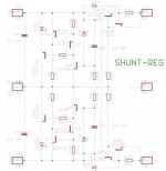
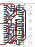
Shunt Regulator
I had another play with this last night. I've uploaded the LTSpice file, the Eagle schematic entry image and a preliminary layout image. The layout is fairly compact as I have very little board space. It's not the last word in regulator design or layout but if it works reasonably well it may prove to be satisfying. Layout: the +/-36V, 0v inputs are at the bottom edge, the +30V output along the top (to the left), 0V in the centre, -3V output along the bottom (to the left) with power devices along the right hand side where they'll bolt to an angle bracket attached to the chassis. The left hand area of the pcb will contain the rest of the Board-1 circuits. Resistor and diodes are all SMD, 1206 size for easy handling (similar size to small through hole parts) and the 3-legged parts are through-hole (for easy dismounting in case of issues).
I had another play with this last night. I've uploaded the LTSpice file, the Eagle schematic entry image and a preliminary layout image. The layout is fairly compact as I have very little board space. It's not the last word in regulator design or layout but if it works reasonably well it may prove to be satisfying. Layout: the +/-36V, 0v inputs are at the bottom edge, the +30V output along the top (to the left), 0V in the centre, -3V output along the bottom (to the left) with power devices along the right hand side where they'll bolt to an angle bracket attached to the chassis. The left hand area of the pcb will contain the rest of the Board-1 circuits. Resistor and diodes are all SMD, 1206 size for easy handling (similar size to small through hole parts) and the 3-legged parts are through-hole (for easy dismounting in case of issues).
Attachments
Last edited:
LED201 is an extremely misguided and wasteful way to purchase extra headroom for current source Q210. As shown it increases the output impedance quite substantially. (Replace it in the simulation by a 1.8V ideal voltage source and notice the huge drop in output impedance).
With the exact same parts count you can make two tiny tweaks and get vastly improved performance. These tweaks increase the gain of the error amplifier (which lowers closed loop output impedance) AND decrease the open loop output impedance (which further lowers closed loop output impedance). Simply
The input impedance looking into the base of the single emitter follower, loads down the error amplifier, which limits its gain. Changing to a darlington increases the input impedance, which boosts error amplifier gain and decreases closed loop output impedance.
Switching to a darlington confers a second benefit as well. Those circuit design textbooks are right: the open loop output impedance of a darlington emitter follower really IS a factor of Beta lower than the open loop output impedance of a single emitter follower. This decreases closed loop output impedance by another factor of 40 or so.
At no increase of parts count you can decrease output impedance by more than 40X simply by improving the design. Easy call IMHO. Put em side by side in the same simulation and compare.
.
With the exact same parts count you can make two tiny tweaks and get vastly improved performance. These tweaks increase the gain of the error amplifier (which lowers closed loop output impedance) AND decrease the open loop output impedance (which further lowers closed loop output impedance). Simply
- replace the VBE + VCE current source (Q209-Q210-R207), by an emitter degenerated current mirror. Thus buys an extra ~400 mV of headroom
- replace Q205-LED201 by a PNP Darlington like the 150 MHz 2SB1257 as suggested in post #162. If you're scared of fast darlingtons there are plenty of slow ones to choose from.
Switching to a darlington confers a second benefit as well. Those circuit design textbooks are right: the open loop output impedance of a darlington emitter follower really IS a factor of Beta lower than the open loop output impedance of a single emitter follower. This decreases closed loop output impedance by another factor of 40 or so.
At no increase of parts count you can decrease output impedance by more than 40X simply by improving the design. Easy call IMHO. Put em side by side in the same simulation and compare.
.
Last edited:
Member
Joined 2009
Paid Member
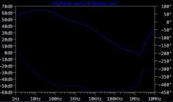
Douglas Self's book "Small Signal Audio Design" has a chapter on phono cartridge output levels,
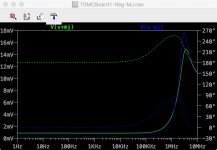
I found it a bit confusing at first with my simulations because the gain of the phono amp has to vary a lot over the frequency range to implement the RIAA curve. A couple of times I had to remind myself that the gain and output levels are often referenced to 1kHz. I've attached the gain curve of the phono amp, the gain is higher than the original NAD circuit because I want the output to be closer to that which might be provided by other source components.
Attachments
Member
Joined 2009
Paid Member
Put em side by side in the same simulation and compare.
I have just done the simulation (had to make a Darlington out of two transistors) and the reduction in Zout is quite shockingly good. Also see a better bode plot because with these changes it appears to retain better OLG to higher frequencies without a stability issue.
My layout is very compact, not sure if these changes will be painful for the layout or not but if I stick with TO-126 parts on the heatsink I'd be looking at BD679 and BD680.
Attachments
Member
Joined 2009
Paid Member
Text books are very useful. Mind you, I do like to take liberties at times, I don't always want a text book solution and prefer to allow a bit of poetic license.
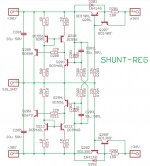
Please check the attached - should have the latest improvements. I haven't seen this exact design anywhere else so there is some risk I've missed something - if you know of a prior use of this design that proves out the circuit that reduces the risk a bit but I do tend to feel comfortable if I've got some reasonable simulation results. The performance, from the simulations, looks sufficient for the task.
The layout was easy to change.
Attachments
Last edited:
- Status
- Not open for further replies.
- Home
- Source & Line
- Analog Line Level
- TGMC - a modular control pre-amplifier