Well I have a few of these gold caps, a couple of them in parallel gives me 20mF. Mine's bigger than yours !
Don't tempt me, I'll bust out the "beer can computer caps" and lengths of hookup wire 😀
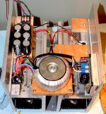
I started building a JLH '69 several years ago including some nice home made pcb's. However, it hit some snags along the way and never got finished. Recently I tested the power supply and found excessive voltage sag under load which leads me to doubt that the transformer is up to the task of a stereo unit so this is going to be a mono block.
The details got spread around in the extensive thread on this topic, starting back in April 2011 [http://www.diyaudio.com/forums/solid-state/3075-jlh-10-watt-class-amplifier-48.html#post2545677] ] and it's hard to keep track of what I was doing so I've opened this thread to capture it and hopefully get the thing finished. Maybe when it's all done the Mods can append this thread to the original monster.
Contraints: I want to use up the bits I have in my junk box and use the half built chasis that I have. This includes all the old RCA 2N3055H's that are rivetted onto the heatsinks. They have date codes spanning 1981 - 1982 (recovered from an e-waste power supply) and I understand they have ft of 2.5MHz. I consider this project a kind of 'industrial archeology', so I won't entertain any notion that these output devices are unsuited. The challenge with older devices is 'beta droop', in other words a significant decrease in input impedance at high current.
The suffix H indicates a Hometaxial device which is the more rugged version. The minimum fT for this variety is 800 kHz as opposed to the Epitaxial one with minimum fT of 2.5 MHz.
RCA changed the designation from 2N3055H to 2N3055 (Hometaxial) by the time of my 1978 edition of their Power Devices handbook. Not that it is a significant point I think other manufacturers deferred to RCA by designating their version as RCA3055H which might explain the date codes between 1981 and 1982 on your cases - perhaps?
A speaker capacitor must be rated for AC duty, unless you arrange for a DC bias to exceed the peak of the AC signal.
You would need to use a series pair of back to back polar electrolytics to achieve that AC capability.
Alternatively you could add a reversed diode across the capacitor to bypass any (excess) reverse voltage during a sustained fault incident.
You would need to use a series pair of back to back polar electrolytics to achieve that AC capability.
Alternatively you could add a reversed diode across the capacitor to bypass any (excess) reverse voltage during a sustained fault incident.
Member
Joined 2009
Paid Member
A speaker capacitor must be rated for AC duty, unless you arrange for a DC bias to exceed the peak of the AC signal.
In the single rail version the output capacitor is kept polarized and the ripple current rating of the caps are 4A at 120Hz; this rating increases by 15% at 10kHz.
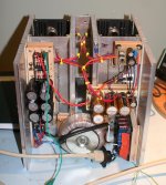
I've made a bit more progress. I've installed the soft-start board and the power supply filter board (photo shows the amplifier chassis lying face down, the back open for installation of the parts). It ain't pretty but I'm having a blast building it with any bits I can find lying around !
Attachments
In the single rail version the output capacitor is kept polarized and the ripple current rating of the caps are 4A at 120Hz; this rating increases by 15% at 10kHz.
I've made a bit more progress. I've installed the soft-start board and the power supply filter board (photo shows the amplifier chassis lying face down, the back open for installation of the parts). It ain't pretty but I'm having a blast building it with any bits I can find lying around !
good work! this circuit, the input ac is a filter dc ?
A speaker capacitor must be rated for AC duty, unless you arrange for a DC bias to exceed the peak of the AC signal.
the DC bias exceeds the AC peak signal and thus the capacitor needs to be rated for the worst case DC condition instead of the worst case AC condition.In the single rail version the output capacitor is kept polarized and the ripple current rating of the caps are 4A at 120Hz; this rating increases by 15% at 10kHz..............!
Member
Joined 2009
Paid Member
good work! this circuit, the input ac is a filter dc ?
Thanks!
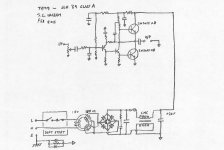
The power supply mains AC input goes through a soft-start circuit but this only delays the main current for a short time, there isn't any filtering there. Then it goes to the main power transformer - a toroidal step-down. Then rectifiers and then dc filter, as you say. This dc filter is 6 x 10,000uF Nichicon capacitors and after that I have two chokes in series. Each choke is rated for 9mH at 3A and are designed to further reduce power supply noise. They will be effective over most of the audio band. At 120Hz the inductors together will have an impedance of around 14 Ohms, but will only produce a dc voltage drop based on it's dc resistance (DCR = 0.1R) which is why I picked inductors instead of resistors. At 12kHz the inducotr will have an impedance of nearly 1k4 so we get more filtering at higher frequencies (at really high frequencies the parasitic capacitance between the inductor windings will spoil it). After the chokes is another 10,000uF Nichicon FW Gold capacitor to form in total a CLC filter.
the capacitor needs to be rated for the worst case DC condition
We should be good, all the large caps are rated for 50V, twice the power rail voltage. I've read that higher voltage caps are better quality than lower voltage caps so perhaps there is some slight advantage.
Last edited:
This does not seem right.................We should be good, all the large caps are rated for 50V, twice the power rail voltage. I've read that higher voltage caps are better quality than lower voltage caps so perhaps there is some slight advantage.
If your 50V capacitors are @ double the rail voltage, then that means you are confirming that your rail voltage is ~25Vdc.
That then confirms your maximum output signal is ~8Vac and into rated load probably less and maybe as much as 1V less.
That would indicate a maximum power output of around 6W to 8W into 8ohms.
Is that right?
Last edited:
Member
Joined 2009
Paid Member
I believe my statement is right.
Regarding power output - I can't get the rail voltage called for by the original JLH design (i.e. at least 27V) so I'll accept a lower power output. Thing is, I'm using this amp to temporarily replace a 6AS7 SE tube amplifier that generates maybe 3W when the sun is shining.
Rather than 25V I expect to have only 24V rails. Maybe, the output stage can get within 2V of the rails (?), giving me +/-10V. Into an 8R load this would be (10*10)/(2 x 8) = 6.25W rms. I'll be quite happy with that.
I'm considering a simple RC filter on the rail instead of a capacitance multiplier. Simulation based on a 10,000uF cap at that location looks like this is able to provide the same benefits. It keeps things closer to the spirit of the original circuit, which appeals to me. However, the simulated performance with the additional output devices, cleaner DC supply for the front end - adds up to a significant performance improvement.
Attachments
Last edited:
You are OK.
I did not realise your TGM9 had a target maximum power of 6W.
On your post29 pic you show a snubber across the output of the bridge rectifier.
It may be better to move it to the input of the bridge rectifier, i.e to the transformer secondaries.
The mains fuse should be before the switch.
I did not realise your TGM9 had a target maximum power of 6W.
On your post29 pic you show a snubber across the output of the bridge rectifier.
It may be better to move it to the input of the bridge rectifier, i.e to the transformer secondaries.
The mains fuse should be before the switch.
Member
Joined 2009
Paid Member
There is no target, just trying to make a JLH69 with parts on hand. It will be enough for the application.I did not realise your TGM9 had a target maximum power of 6W.
I think this was discussed already - it is where it is, no plans to move it now.On your post29 pic you show a snubber across the output of the bridge rectifier. It may be better to move it to the input of the bridge rectifier, i.e to the transformer secondaries.
this is a limitation of the design of the soft-start circuit (eBay). Not perfect at all, I will think about this.The mains fuse should be before the switch.
Anyhow....
Some progress!
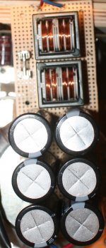
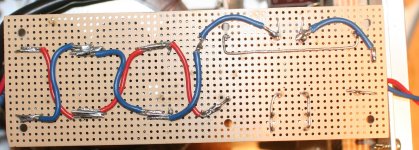
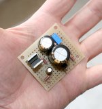
The power supply board is done, big black caps. The underside wiring is 'very DIY' !
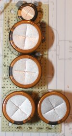
Also found some more perf board in the scrap box to hold the big gold caps. These are the final rail cap, output caps and front-end filter cap. And a Nichicon MUSE cap for the bootstrap. Underside wiring even more crazy! Next step is to find some more perf board to build the input stage.
I checked it out be rewiring it up again as a Follower. Get V+ of 24V at idle. My multimeter 'sees' around 17mV of a.c. ripple. I'll get a CRO on it once more of the amp is built.
Attachments
Last edited:
Member
Joined 2009
Paid Member
Last board.
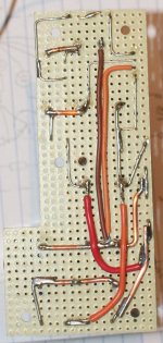
I found and cut a small piece of prototyping board for the small signal circuitry - all the parts around the input device. And I included on the board two back-to-back TO-220 diodes from the scrap bin to form the earth loop interruptor between signal ground and chassis.
I used Dale 1% resistors all-round (happen to have them in the parts bin)
I also used Nichicon Gold (and MUSE) 50V rated capacitors all-round. Even the input cap is an electrolytic. It will be polarized (approx. 10V) and at 10uF it will have little a.c. voltage across it.
A small 470pF NPO/C0G cap was used for the input rf-filter. I like these too.
For the input device I found a nice 2SA844 pulled out of something old - a very good quality transistor, possibly over-spec'd here.
For the phase splitter, TR3, I found a nice 2SC3419, also pulled out of something old. These devices have a low Vsat (nice for lower power rails) and tolerate a lot of collector current if things go pear shaped.
Attachments

Last edited:
Member
Joined 2009
Paid Member
Have now powered it up to check that dc-conditions are OK.
Adjusted dc-offset at output (before cap) to half the power rail voltage.
The voltage drop across the power supply chokes is 272mV which equates to 1.6A draw by the amplifier. About 22mA flows through the bootstrap current source to TR3. It looks as if all is good at dc.
A more careful analysis of current flows tells me that the average Hfe of the power devices is 146, a reasonable number judging by the spec. sheet for 2N3055.
Attachments
Member
Joined 2009
Paid Member
Got the CRO out. Hooked up an 8R load to the output.
Some images:
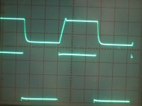
First up (left) - power supply output ripple. Looks nice and smooth, 120Hz with 50mV pp on the +ve rail. The output of the amp shows only 2mV to 3mV pp of ripple
Second up (middle) - 1kHz square wave 500mV pp input (test point output on scope); output looks reasonably clean and at 5.2V pp we see the gain is around X10.4
Third up (right) - hooking up a signal generator provide a 20kHz square wave input (lower trace - not that clean itself). See some ugliness now on the leading edge of the output (upper trace) which was unexpected; some of this is crap from the poor signal generator.
And,
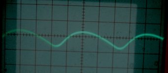
With a sine wave input the output triangulates at 100kHz, but it's amplitude dependent and the triangulation appears only above 3V pp at 100kHz. The input r.f. filter would not cause this so it a limitation of the amplifier (slow output devices ?)
Clipping was explored using a 1kHz sine wave and turning up slowly till I could see the tops flatten in the output waveform - i see it is very close to being symmetrical at an output of 22V pp. Implication is a peak output of roughly 7W into 8R.
Some images:
First up (left) - power supply output ripple. Looks nice and smooth, 120Hz with 50mV pp on the +ve rail. The output of the amp shows only 2mV to 3mV pp of ripple
Second up (middle) - 1kHz square wave 500mV pp input (test point output on scope); output looks reasonably clean and at 5.2V pp we see the gain is around X10.4
Third up (right) - hooking up a signal generator provide a 20kHz square wave input (lower trace - not that clean itself). See some ugliness now on the leading edge of the output (upper trace) which was unexpected; some of this is crap from the poor signal generator.
And,
With a sine wave input the output triangulates at 100kHz, but it's amplitude dependent and the triangulation appears only above 3V pp at 100kHz. The input r.f. filter would not cause this so it a limitation of the amplifier (slow output devices ?)
Clipping was explored using a 1kHz sine wave and turning up slowly till I could see the tops flatten in the output waveform - i see it is very close to being symmetrical at an output of 22V pp. Implication is a peak output of roughly 7W into 8R.
Attachments

Last edited:
Good work Gareth; this one has a very DIY feel about it: everything laid out on Veroboard and a custom designed case 
Member
Joined 2009
Paid Member
That's just how I feel about it ! - whilst the TGM8 was semi-pro, this JLH69 variant gave me a great deal of pleasure during the past few weeks. I felt like a kid again. 
Well, I hooked up an iPad source (iTunes) and tried it out with my Moon Oaken speakers (Mark audio CHN70). I was underwhelmed, although it did produce music. I tried my B&W floor stander. There as bass punch but the sound was rough. What the hell is this.
After taking a break I thought the source needed upgrading. I also noticed the input connector was lying on the power cord, not the best. I put my Bryston BP60 in place as a pre-amp to give me a volume control. I then fed that with my YBA CD player and pulled out some Dianna Krall with the B&W floor stander still in place.
Well - the music poured forth without a blemish, pure honey ...I switched back to the small full range MA CHN70 in my Moon Oaken box. The clarity was superb, smooth as silk.
This poor mans junk box amplifier has surprised me. More extensive listening will be required and perhaps it'll warrant a comparison with my other amplifiers.
Last edited:
The middle pick shows overshoot.
This is usually more visible by upping the sqw frequency or using the horiz times 10 switch.
I recommend you ALWAYS endeavour to eliminate overshoot of a sqw test signal.
Overshoot and ringing can look a lot better if the input filter rolls off the HF.
Overshoot and ringing can look excessive if the input filter is disabled AND a too fast sqw test signal is applied.
One needs a happy medium for the speed (rise/fall time) of the test signal.
Is the rightmost pic confirming that the test signal has overshoot?
Could the test signal be seeing the wrong impedance and it's a reflection of the fast signal that is creating the overshoot?
Is the generator a 50ohms source impedance?
Is the cable a 50ohms impedance?
Is the load at the amp PCB a 50ohms impedance?
Last edited:
Member
Joined 2009
Paid Member
I haven't had much time to work on this of late and that time was spent working on the chasis. I'm not a huge fan of chasis work because I don't have a proper workshop and rely on a power drill and other hand tools.
Yes, it's a real possibility because the test set up was not optimized to avoid impedance mismatch - there were probably several points where a reflection could occur. However, despite my poor experimental technique I've had clean waveforms from testing of other amplifiers I've built.
The waveform shown on the right (my post above) shows not only an overshoot on the +ve edge but that the shapes of the edges are different from each other.
Yes, it does look as if the test signal isn't clean itself, both +ve and -ve going edges.Is the rightmost pic confirming that the test signal has overshoot?
Could the test signal be seeing the wrong impedance and it's a reflection of the fast signal that is creating the overshoot?
Yes, it's a real possibility because the test set up was not optimized to avoid impedance mismatch - there were probably several points where a reflection could occur. However, despite my poor experimental technique I've had clean waveforms from testing of other amplifiers I've built.
The waveform shown on the right (my post above) shows not only an overshoot on the +ve edge but that the shapes of the edges are different from each other.
Member
Joined 2009
Paid Member
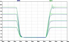
I thought I'd feed a square wave into my simulated circuit to see how it behaves and what I see looks qualitatively similar to the measured waveform. At low signal levels it's clean but the +ve edge starts to show over-shoot at higher signal levels.
The attached plot shows several different signal levels for a 10kHz square wave, both for the original JLH69 (blue traces) and the TGM9 (green traces) version.
The attached plot shows several different signal levels for a 10kHz square wave, both for the original JLH69 (blue traces) and the TGM9 (green traces) version.
Attachments
Member
Joined 2009
Paid Member
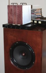
First Listening Test on the Big'un Speaker
So I've put some bits of metal and wood on the chassis to make it presentable. And I've installed it on top of my slimline Bryston integrated (using it as a pre-amp) so I can play it through my Audio Nirvana 15" open back box speaker. Source is an FM tuner on the local French channel (they seem to have the best sound quality of all the FM stations I can pull in with a simple antenna).
It sounds quite different from my SET. The bass is stronger, cleaner and deeper. It sounds just as smooth as the SET amp. 🙂
🙂
And of course, with 7,000mW of power it beats my SET amp (which may have 2W or so). I'll need to hook up my CD player for some more critical listening.
So I've put some bits of metal and wood on the chassis to make it presentable. And I've installed it on top of my slimline Bryston integrated (using it as a pre-amp) so I can play it through my Audio Nirvana 15" open back box speaker. Source is an FM tuner on the local French channel (they seem to have the best sound quality of all the FM stations I can pull in with a simple antenna).
It sounds quite different from my SET. The bass is stronger, cleaner and deeper. It sounds just as smooth as the SET amp.
🙂 And of course, with 7,000mW of power it beats my SET amp (which may have 2W or so). I'll need to hook up my CD player for some more critical listening.
Attachments
Last edited:
- Home
- Amplifiers
- Solid State
- TGM9 - my version of the JLH '69 Class A amplifier