I ordered my TGM8 boards from itead. Quality was excellent. Unfortunately, I have none to sell. I originally planned to build just two boards but liked the TGM8 so much that I built six (four to power my LXmini and two for my home office).
Note these boards are densely populated and have about 30 SMD components. This is probably not something you can throw together in an evening. The end result is definitely worth the effort.
Note these boards are densely populated and have about 30 SMD components. This is probably not something you can throw together in an evening. The end result is definitely worth the effort.
Member
Joined 2009
Paid Member
In response to an enquiry I received via PM see the attachments.
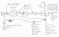
"Lastly, for wiring up the chassis ..."
The star earth point is not connected to the chassis except through the back-to-back diodes. This 'trick' is used to isolate the amplifier ground from mains ground and reduce the issue of ground loops causing hum.
"Lastly, for wiring up the chassis ..."
The star earth point is not connected to the chassis except through the back-to-back diodes. This 'trick' is used to isolate the amplifier ground from mains ground and reduce the issue of ground loops causing hum.
Attachments
Last edited:
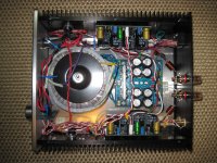
With some prodding from Bigun, I've posted some pictures and details about my TGM8
build completed late last year.
Chassis is an ebay 2409-2 with a custom 0.125" aluminum baseplate. Heatsink
thickness is only 7mm which is a bit marginal (some other ebay chassis have heatsinks
as thin as 5mm!). I was worried about noise with so much stuff crammed into a small
chassis but this amplifier actually is very quiet.
Transformer is an Antek AS-2228 (240VA, 28V); rail voltage at idle is about 39V.
Something like 480VA would be a better match for a pair of TGM8 boards but this
would be expensive overkill for my particular application.
I used Sanken 2SA1492/2SC3856 for the output BJT transistors as these are reported
to sound better than the default 2SA1943/2SC5200. My build also includes an
IRFP240/IFRP9240 even though I doubt these class C only-when-it-gets-loud transistors
will be active with my fairly efficient speakers.
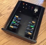
This is one of my favourite amplifiers. Sound quality, particularly bass, is excellent. I
appreciate the built-in speaker protection which makes this amplifier more of a complete
product safe to use with expensive speakers. Thankyou, Gareth, for sharing your
design with us.
build completed late last year.
Chassis is an ebay 2409-2 with a custom 0.125" aluminum baseplate. Heatsink
thickness is only 7mm which is a bit marginal (some other ebay chassis have heatsinks
as thin as 5mm!). I was worried about noise with so much stuff crammed into a small
chassis but this amplifier actually is very quiet.
Transformer is an Antek AS-2228 (240VA, 28V); rail voltage at idle is about 39V.
Something like 480VA would be a better match for a pair of TGM8 boards but this
would be expensive overkill for my particular application.
I used Sanken 2SA1492/2SC3856 for the output BJT transistors as these are reported
to sound better than the default 2SA1943/2SC5200. My build also includes an
IRFP240/IFRP9240 even though I doubt these class C only-when-it-gets-loud transistors
will be active with my fairly efficient speakers.
This is one of my favourite amplifiers. Sound quality, particularly bass, is excellent. I
appreciate the built-in speaker protection which makes this amplifier more of a complete
product safe to use with expensive speakers. Thankyou, Gareth, for sharing your
design with us.
Attachments

Member
Joined 2009
Paid Member
Hey that looks really good - glad you posted some photos.
Funny about that heatsink, I had the same problem - actually I think I have the cheap-chinese 5mm version - so I had to ask a local chap to make some tapped holes for me as it was beyond my experience. My chassis is not ready yet, but it looks quite similar to yours, we might have the same one, more or less. I wasn't going to post my work-in-progress but you have inspired me to do so 😎
Funny about that heatsink, I had the same problem - actually I think I have the cheap-chinese 5mm version - so I had to ask a local chap to make some tapped holes for me as it was beyond my experience. My chassis is not ready yet, but it looks quite similar to yours, we might have the same one, more or less. I wasn't going to post my work-in-progress but you have inspired me to do so 😎
Attachments
Last edited:
JFET input stage option?
Hi Bigun,
I built your TGM8 with LATFET outputs and have been very happy with it. This was the TGM8 basic version.
I was wondering if there was a JFET input stage (singleton with ccs) design?
Hi Bigun,
I built your TGM8 with LATFET outputs and have been very happy with it. This was the TGM8 basic version.
I was wondering if there was a JFET input stage (singleton with ccs) design?
Last edited:
Hi Auriga, I've been following this thread since the start and I can safely say there is no version with a JFET input transistor, certainly none that has been shown here.
Why don't you have a go at drawing it yourself and posting here in this thread? Have a look at how the JFET input is biased on the FetZilla design also on this forum.
Why don't you have a go at drawing it yourself and posting here in this thread? Have a look at how the JFET input is biased on the FetZilla design also on this forum.
Member
Joined 2009
Paid Member
I've yet to build anything with JFETs although I love the concept. What I've struggled with for JFET projects is that they tend to have a lot of variability so in some circuits you gotta test and select and most of the choices these days are surface mount devices. They have always intrigued me because of being depletion mode devices and I find their principle of operation quite elegant. I think it would be an excellent idea to try one at the input of the TGM8 amp - as suggested by Ranchu32
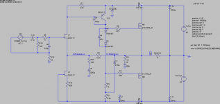
The jFET bias is set by J2 and R10
The gain is set by R5 : R13 and equals 23times (+27.2dB) in the passband.
THD unknown until you test it.
The gain is set by R5 : R13 and equals 23times (+27.2dB) in the passband.
THD unknown until you test it.
P3A PCB
Hello All P3A builders
I found Rod Elliott P3A amp PCB on the following link https://elprojects.wordpress.com/201...amplifier-p3a/
I already check this PCB layout with Rod Elliott original P3A Schematic, found This PCB layout is ok.But have some component value changes, Can I use this PCB with Output as Tip 35/36 on +/-35VDC.Bellow, I attach All layers Pcb layout of Mr M.Mahai. please help.
Attachments
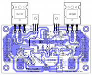
Power inputs on opposite sides of the PCB with a long Power Ground trace does not work well.
Yet this is the way most layout designers do it !
The length of the power ground trace introduces high impedance at higher frequencies and ruins any effect that Local supply rail decoupling can hope to achieve.
Yet this is the way most layout designers do it !
The length of the power ground trace introduces high impedance at higher frequencies and ruins any effect that Local supply rail decoupling can hope to achieve.
Hi Bigun,
Several months ago we had talked about something for an amplifier and the conversation lead to the discussion of your TGM8. You had graciously shared your gerbers so I could run a small batch of TGM8 PCBs, which I had done and then left the project on the shelf for some time since I had a few other things to do.
Got all the parts for the BoM recently and finally started the project, ahead of other amp projects I had planned before since I was really curious.
So, for one I'd like to take the time and thank you for sharing this beautiful project which I'm currently assembling. Here's a picture of the work so far (all SMD soldered on bottom layer as well).

Thanks again for all the support so far!
Do
Several months ago we had talked about something for an amplifier and the conversation lead to the discussion of your TGM8. You had graciously shared your gerbers so I could run a small batch of TGM8 PCBs, which I had done and then left the project on the shelf for some time since I had a few other things to do.
Got all the parts for the BoM recently and finally started the project, ahead of other amp projects I had planned before since I was really curious.
So, for one I'd like to take the time and thank you for sharing this beautiful project which I'm currently assembling. Here's a picture of the work so far (all SMD soldered on bottom layer as well).
Thanks again for all the support so far!
Do
Member
Joined 2009
Paid Member
That's some very nice neat work I can see there !
With my fat-fingers and the rather small board it it definitely helped to think about the order of parts assembly, so that you can clean the flux off as you go, and to fit the parts to the board without too much interference or challenges accessing pads with the soldering iron. I use freeware Eagle so board size was artificially constrained! - this is not a beginners build. I did like you, fit the SMD parts first.
The 'spacers' that solder underneath between the power devices and underside of pcb were a bit fiddly if I remember - best to bolt them to the board and centre them as best possible before soldering. The power devices should have their pins bent appropriately then bolt all of them to the heatsink first (oriented as necessary for final assembly of course) - double check all the parts are in the correct places - check again, and again, then mount the board over the power devices with the legs poking through the board - tighten it all down so that the power devices are flat against the 'spacer' devices - the whole sandwich should be flat and stable - only then do you solder the power device leads in place. This ensures the power devices are all flat to the heatsink and parallel to the pcb. You can guess how I found out this was the better way to do it - doh !
I notice that you've built a lot of interesting stuff, I hope the results of this design live up to your expectations !
I will add a caveat, one that never occurred to me before and true for all my projects - I never tested my designs to destruction in terms of how robust they are to various possible failure modes.
Last edited:
I do need to build these project, the SMD parts a bit discouraging, also the 4 large caps has very small room there. Only certain type of caps feet there. 😀
Member
Joined 2009
Paid Member
I feel your pain Gabor !
When I made this design I was a bit younger, a bit more cowboy 😀
If there was a large interest in the design, it might be worth me making an easier-to-build version but I would still use SMD, just a bit more space around the parts. That would take some time and $ and there's no real incentive to do that. The SMD parts are actually the easy part. It's the rest of it you should be worried about.
Last edited:
SMD is really not that hard to do. I suggest to look at some youtube videos. I've been doing SMD for several years but even when I started it was easy to get the hang of it. It's just easy to lose parts though.. I always buy 1-2 spares of each, they're so cheap anyways.
I made progress tonight, almost all done!
Bigun, what are your thoughts about using polymer caps for C7, C20? Better to use regular ones? I have both types in stock. Although C20 probably wouldn't need anything like that...
Thanks
Do
I made progress tonight, almost all done!
Bigun, what are your thoughts about using polymer caps for C7, C20? Better to use regular ones? I have both types in stock. Although C20 probably wouldn't need anything like that...
Thanks
Do
Member
Joined 2009
Paid Member
Bigun, what are your thoughts about using polymer caps for C7, C20? Better to use regular ones? I have both types in stock. Although C20 probably wouldn't need anything like that...
Agreed, C20 may as well stick with regular. It's possible C7 could benefit, but I doubt I would be able to hear a difference. If you believe the polymer to be a better cap then why not use it - personalizes the build a little 🙂
I just realized that R10 (series feedback res) is 1/2W instead of 1W as per BoM. Should I change this or I'm fine with 1/2W?
I just need to clean the underneath of the PCB, then I can fire up this amplifier for testing.
Thanks
Do
I just need to clean the underneath of the PCB, then I can fire up this amplifier for testing.
Thanks
Do
Very neat soldering, pinnocchio. You will not be disappointed with this amp!
Thanks!
SMD is somewhat therapeutic for me! LOL
Do
- Home
- Amplifiers
- Solid State
- TGM8 - my best amplifier, incredible bass, clear highs, no fatigue (inspired by Rod Elliot P3a)