Andrew - can you post one of the designs you have in mind up here, it might provide a great example to learn from ?
I browsed through JLH's schematics on the Class A Amplifier website here: The Class-A Amplifier Site
He had a penchant for for the VN1210 for the VAS transistor - an N channel depletion mode MOSFET - featured in many of his designs from the 80's and 90's.
http://sound.au.com/tcaas/ETI7-84.gif
http://sound.au.com/tcaas/EWW3-89.gif
http://sound.au.com/tcaas/ETI5-89.gif
http://sound.au.com/tcaas/EWWW6-93.gif
http://sound.au.com/tcaas/EWWW6-93.gif
I couldn't find any with a JFET VAS. Andrew?
Looks like I don't know the difference between jFET and VN1210.
Sorry.
Note also the lack of Cdom in all of those designs.
This is typical of many British designers.
Sorry.
Note also the lack of Cdom in all of those designs.
This is typical of many British designers.
Last edited:
Member
Joined 2009
Paid Member
The only data sheet I could find easily was from Supertex and it says the VN1210 is an enhancement mode device ?
Of course, with a FET VAS there's already a fair bit of capacitance so additional external Cdom may not be needed or at least may be limited in value.
Of course, with a FET VAS there's already a fair bit of capacitance so additional external Cdom may not be needed or at least may be limited in value.
Member
Joined 2009
Paid Member
If someone order PC boards I'm up for a pair.
Some place has minimum order if that helps, please let me know.
Thank you
Greetings Gabor
Some place has minimum order if that helps, please let me know.
Thank you
Greetings Gabor
Member
Joined 2009
Paid Member
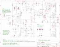
TGM8 (B)
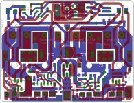
I might have a couple of boards left. However, it might also be of interest to have a revised layout, which incorporates the following:
i) Added C25, a 10uF 25V SMD 1210 part in parallel with the zener diode D1 as per post 297
ii) Inserted D8, a small signal diode 1N4148 SOD-123 part between the opto-coupler pin 3 and ground, as per post 314 (with R39 changed to 750R)
iii) Resized the main filter cap pad drill size to 2mm to better match the snap-in caps specified
iv) Fixed silk screen error ('bias' and 'offset' descriptions were transposed)
v) Updated the copyright for 2014 version B
I recommend you buy the boards from here, prices are excellent (there's a sale on right now!), service has been very good and I've been pleased with the quality: ITEAD Studio 2Layer Green PCB 5cm x 10cm Max
I ended up using the cheap green boards, but maybe Ranchu has found the coloured boards to sound better 😀
Attachments
Last edited:
Nice one Gareth, good to see this design updated and the and the Eagle files released (I'm looking at them now).
I can attest to the wonderful results from my BLUE boards... I doubt the green ones sound as good but YMMV :-D
I can attest to the wonderful results from my BLUE boards... I doubt the green ones sound as good but YMMV :-D
Member
Joined 2009
Paid Member
Maybe the RED ones would be even better ? 🙂
Well I hope you are enjoying it. As I said once before, this is my last ground-up SS amplifier design; I couldn't have 'gone out' with anything less than the sound TGM8 produces to my ears. After this I will mess about with some odd stuff, JLH, tubes and whatnot.
Well I hope you are enjoying it. As I said once before, this is my last ground-up SS amplifier design; I couldn't have 'gone out' with anything less than the sound TGM8 produces to my ears. After this I will mess about with some odd stuff, JLH, tubes and whatnot.
How can you throw in the towel when you haven't tried a fully symmetrical design with complimentary LTP input stage and EF triple using latfet outputs?
Member
Joined 2009
Paid Member
How can you throw in the towel when you haven't tried a fully symmetrical design with complimentary LTP input stage and EF triple using latfet outputs?
Sounds complicated - something for you to champion 🙂
Mind you, my 2nd fully symmetrical amp, TGM7, uses complimentary LTP and FET outputs and sounds superb. I don't see any reasonable scope for improvement as far as fully symmetrical amps go and consider TGM7 to be comparable with TGM8.
Nope, I'm quite happy to rest on what I've done with SS power amps so TGM8 is the end of the road for me. Life's short and there's a JLH69 to finish up as well as other things to learn about.
I would like to have a go at a SS-assisted vacuum tube amplifier which if I get around to it you will see here as TGM9 but I don't plan a series of hybrids, just the one possibility. 😎
Last edited:
Hi Bigun
As you know, I am building a special amp that uses your input stage. Please leave your comments here: http://www.diyaudio.com/forums/solid-state/258549-assemblage-power-amp.html#post3978099
As you know, I am building a special amp that uses your input stage. Please leave your comments here: http://www.diyaudio.com/forums/solid-state/258549-assemblage-power-amp.html#post3978099
Member
Joined 2009
Paid Member
Hi RC - your amp is coming along nicely. However, you didn't feel brave enough to use the full version of my input stage i.e. 3 BJTs total 🙂
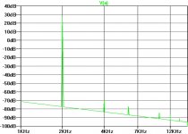
As an fyi, this is what my simulation file spits out for TGM8 based on +/-35V into an 8R load at 2kHz (just like your speaker 😉 ) for the FFT profile - note the Hiraga-like fall off, which is somewhat irrelevant when you consider this is a theoretical simulation and it shows all harmonics at around -100dB or lower which likely bears no resemblance to reality 🙂
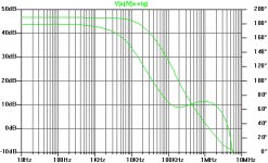
And the 2nd plot comes from placing a signal source in the feedback loop to examine the fall off in OLG (upper trace) and corresponding phase shift (lower trace). Not sure if this is a valid way of doing it - I think it shows a 60 degree phase margin.
As an fyi, this is what my simulation file spits out for TGM8 based on +/-35V into an 8R load at 2kHz (just like your speaker 😉 ) for the FFT profile - note the Hiraga-like fall off, which is somewhat irrelevant when you consider this is a theoretical simulation and it shows all harmonics at around -100dB or lower which likely bears no resemblance to reality 🙂
And the 2nd plot comes from placing a signal source in the feedback loop to examine the fall off in OLG (upper trace) and corresponding phase shift (lower trace). Not sure if this is a valid way of doing it - I think it shows a 60 degree phase margin.
Attachments
Last edited:
I am just starting..... I feel braver now 🙂
Once I get the Vbias and output stage figured out, I will consider cascading the VAS as per your schematic.
BTW... incredibly good THD figures you have got.
Once I get the Vbias and output stage figured out, I will consider cascading the VAS as per your schematic.
BTW... incredibly good THD figures you have got.
Member
Joined 2009
Paid Member
Good - be brave!
THD - that extra BJT bootstraps the input device - much improved linearity, higher OLG (feedback does wonders when used well) and then add two pole compensation - the icing on the cake as far as the simulated results are concerned. But this is only simulations and likely not easily realized - and likely not the right thing to be worried about - the key is that my ears like the results 😀
THD - that extra BJT bootstraps the input device - much improved linearity, higher OLG (feedback does wonders when used well) and then add two pole compensation - the icing on the cake as far as the simulated results are concerned. But this is only simulations and likely not easily realized - and likely not the right thing to be worried about - the key is that my ears like the results 😀
Last edited:
You just made me itch.... will now implement the extra bjt.... Just need some extra explaining.... how does the two pole compensation work ?
PS: Please have a look at my THD sim in the "Assemblage"
PS: Please have a look at my THD sim in the "Assemblage"
Member
Joined 2009
Paid Member
It's beyond the scope of my brain to explain fully two-pole-compensation but there are lots of references out there (on the web). The way I see it - as frequency goes up there is more and more phase shift through the amplifier (from inductance/capacitance/resistance) and eventually you get to a frequency where the phase shift is too much (180 degrees) and you -ve fdbk is +ve. So you add low-pass filter to roll-off the gain at high frequencies so that the signal is no longer amplified once the phase shift is too large. Making this low pass filter with a single capacitor at the VAS makes the high frequencies roll-off at a certain rate. In order to have a stable amp it has to start rolling-off pretty early so you get less feedback at audio frequencies where you need it and so distortion is higher. But by using a two capacitor network you can create a low pass filter at the VAS with two different rates of high frequency roll-off so that you can keep high gain & feedback at high audio frequencies but still roll-off the gain quickly (more steeply) once phase shift gets excessive. You reduce distortion in the treble but still keep the amplifier stable.
I hope I said that right.
I hope I said that right.
As a small digression /suggestion :
Consider using a pair if Tannoy 15's Or 12" DC.s
A "significant" 🙂 sound quality improvement over the AN's.
Unfortunately not inexpensive in this age of Greed.
Consider using a pair if Tannoy 15's Or 12" DC.s
A "significant" 🙂 sound quality improvement over the AN's.
Unfortunately not inexpensive in this age of Greed.
Member
Joined 2009
Paid Member
I'd be very interested to hear some legendary Tannoy's. A good amp is nothing without a good speaker. However, the AN15" I have is still doing very well for my ears. I'm currently comparing it with a pair of well-run-in Alpair 10.3 Pencil's that I made for a friend and are on loan back to me for a couple of weeks. These are really superb drivers but I haven't got my TGM8 wired up right now because I haven't got the tools to make the holes in the heatsink of the new box I got, so all listening tests use my DIY Cellini amplifier.
It's beyond the scope of my brain to explain fully two-pole-compensation but there are lots of references out there (on the web). The way I see it - as frequency goes up there is more and more phase shift through the amplifier (from inductance/capacitance/resistance) and eventually you get to a frequency where the phase shift is too much (180 degrees) and you -ve fdbk is +ve. So you add low-pass filter to roll-off the gain at high frequencies so that the signal is no longer amplified once the phase shift is too large. Making this low pass filter with a single capacitor at the VAS makes the high frequencies roll-off at a certain rate. In order to have a stable amp it has to start rolling-off pretty early so you get less feedback at audio frequencies where you need it and so distortion is higher. But by using a two capacitor network you can create a low pass filter at the VAS with two different rates of high frequency roll-off so that you can keep high gain & feedback at high audio frequencies but still roll-off the gain quickly (more steeply) once phase shift gets excessive. You reduce distortion in the treble but still keep the amplifier stable.
I hope I said that right.
Quite eloquent.
I will now work on this idea and import it to the "Assemblage".
- Home
- Amplifiers
- Solid State
- TGM8 - my best amplifier, incredible bass, clear highs, no fatigue (inspired by Rod Elliot P3a)