Member
Joined 2009
Paid Member
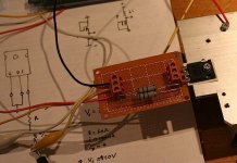
A bit of progress - have installed the passives, diodes and temp sensing transistors. It needs a clean up to remove the solder flux. I didn't install the feedback compensation cap yet. Turns out I have the wrong parts. The design calls for 6pF silvamica but I have 22pF silvamica or 10pF np0 so I'm not sure whether to go with what I have or re-order.
I need to do some device matching before I can progress much more which I may be able to tackle this weekend.
I need to do some device matching before I can progress much more which I may be able to tackle this weekend.
Attachments
Very nice board!A bit of progress - have installed the passives, diodes and temp sensing transistors. It needs a clean up to remove the solder flux. I didn't install the feedback compensation cap yet. Turns out I have the wrong parts. The design calls for 6pF silvamica but I have 22pF silvamica or 10pF np0 so I'm not sure whether to go with what I have or re-order.
I need to do some device matching before I can progress much more which I may be able to tackle this weekend.
22pf in series with 10pf gives 6.8pf. At least to test your board you can try it🙂
Fab
Buy a dozen of each E12 value from 2p2F to 100pF............The design calls for 6pF silvamica but I have 22pF silvamica or 10pF np0.............
What have you decided to use for output devices?
This is his public release I take it? I'm not a member so I can't see
the schematic, I will try to join but if someone could post it for historical
reasons that might be simpler:
SKA sponsored Audio Forum - GB150D design now public domain!
I have a bunch of the original output and therefore want to take a closer
look at the design. I do remember his early threads on the amp.
Hi Bigun,
Nice PCB! I like the compact high current section (with small loops).
PCB availability? 🙂
Nice PCB! I like the compact high current section (with small loops).
PCB availability? 🙂
Member
Joined 2009
Paid Member
What have you decided to use for output devices?
This is his public release I take it? I'm not a member so I can't see
the schematic[/url]
I have a bunch of the original output and therefore want to take a closer
look at the design. I do remember his early threads on the amp.
Hi,
I have decided to build using the output devices that Greg suggests. I still have interest in the QFETs but I didn't want to do the engineering work needed to accommodate these devices since their characteristics are slightly different. In using the same devices as the original GB150 I will at least have a baseline.
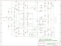
I am not using the public release schematic as-is but have made some modifications. You need to join the forum to see the schematics I suppose but I am attaching the schematic that I used to generate my pcb layout using EAGLE.
If you are interested in Greg's public release design without changes I strongly suggest you buy his pcb - the price is reasonable and it makes little sense going to the time and effort to recreate it yourself (plus what would you learn?).
Hi Bigun,
Nice PCB! I like the compact high current section (with small loops).
PCB availability? 🙂
I would suggest waiting to see if it works before considering any interest in the pcb I've designed. It hasn't been designed for wider use - meaning that it's a fairly compact design that was intended for my use, others may find it more fiddly to assemble than Greg's kit. But if it works and there is interest I have no issues making available the design at least and then we can see where that leads us.
Attachments
Last edited:
Member
Joined 2009
Paid Member
Member
Joined 2009
Paid Member
Member
Joined 2009
Paid Member
Member
Joined 2009
Paid Member
Phew... it powers up on my bench supply +/- 20V, the bias current and dc offset are both smoothly adjustable. It might be slightly over compensated, after 5-10 minutes the bias current fell from 130mV per rail to 110mV per rail; the dc offset appears rock-solid at 0mV. So far no smoke so at least dc-wise it appears first power-up is a success 
Member
Joined 2009
Paid Member
I hooked up a temporary connection to my daughters ipad since it is portable enough to move to my bench. Tried listening to the output on a Paradigm speaker I got from the e-waste. Sounded crap, no volume and hum to kill. 
Ooops, I connected only the centre conductor of the RCA input so I essentially had a large antenna for the input. It was a quick fix to get the input earth connected. Voila - music ! Now it was loud and clear, but to my ears it still sounded crap. These Paradigms need to go back into the e-waste, they are truly awful.
That left me no choice but to haul one of my 3-way B&W CM4's into the hobby room. This made all the difference as I could now hear the amplifier and it gave me no reason to feel disappointed!
Unfortunately, playing MP3's from an ipad isn't a test of the sound quality by any means but I wanted to hear the darn thing play. There was no lack of high's and no lack of low's but of course MPEG doesn't do wonders for the mid-range. Impression: The bass was prodigious and this is on a +/-20V bench supply with 200mA idle per rail.
Clearly it needs a better source and a proper supply before I can listen properly and I am currently using a 10pF np0 on long wires that needs a nice silva mica.
So Sam, I'd say it has quite a bit of potential. Stay tuned.🙂
Last edited:
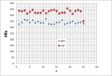
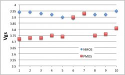
IRFP9240 and IRFP240 Vgs measurement at current of 120mA (p-type is -Ve)
Hi Bigun,
Did you match each mosfet at 60mA for the total bias be 120mA or each at 120mA?
The standard bias current is 100mA. Because there are 2 pairs of mosfets, shoudn't each mosfet be matched at about 50mA?
Member
Joined 2009
Paid Member
Hi Paulo,
I believe the MOSFET bias is something you can readily experiment with as it is so easy to adjust - and with the pcb I have designed it is adjustable when the whole system is assembled - possibly even with the cover on the chasis.
My initial trials were done with a bench supply with built in current limit and meter so I simply used the built in meter to get an approx indication of total current draw by the amplifier. Since the MOSFET idle current dominates the total current draw of the amplifier the power supply current flow was a reasonable indicator of MOSFET bias. I set it around 200mA per rail so each MOSFET was at around 100mA each - but I didn't check the actual balance between them although the Vgs were well matched. I will have a chance to do more measurements once the power supply is built because until then I don't have the design target +/-50V rails.
I have made some progress on the power supply in terms of collecting the parts. I'm short two capacitors but I have enough to re-start the build process. I also got some gorgeous chasis mounting RCA jacks on D-flages made by Amphenol and some nice solder - the first time I have ever purchased solder in my life. The roll I've been using is 40 years old and was a gift from my father but it's getting down to the last few feet.
PCB: I notice that somebody has a PCB for the original SKA150 for sale on eBay (which I feel is inappropriate since this is still a product Greg sells). As a result of the eBay listing I assume interest in my pcb will be minimal to none and as I have no plans to revise my pcb anybody who's interested should PM me.
Last edited:
Member
Joined 2009
Paid Member
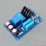
I have now got myself a soft-start module from eBay:
Amplifier Board Sound Power Start Protection High Power Soft Start Board | eBay
A little thought about the feedback compensation cap. I have simulated this. It does need to be in the range of a few pF. With 1pF it's not stable, and above 10pF the stability actually is degraded slightly. There is sweet spot. But the impact is really at high frequencies, it doesn't eat into the audio range at all. Therefore, I can't see the need for an audiophile silver mica cap here. This is Greg's amp and he says otherwise, but the science really doesn't support it at all. It looks to me as if a good quality np0 cap is perfectly good choice. Now, a Lin / Self / RCA topology amplifier has a Cdom compensation cap that does participate in the roll-off at the top end of the audio range and I can see why the quality of this cap is critical. But that's not true of TGM7. Just a thought.
Attachments
Last edited:
I will say one thing Gareth - Greg never uses 'boutique' parts without having a very good explanation. Why don't you ask him? He'll have a reason for sure.
Member
Joined 2009
Paid Member
I did ask - Greg says to use a high quality cap such and an example would be Silva Mica. However, Silva Mica has relatively higher DA, a reason why you can use less capacitance when using Silva Mica for Cdom than if using NP0. NP0 have very good spec, they are not your Grandfathers type of ceramic. Old amps sometimes had poor (cheap high k) dielectric ceramics and poor (old technology) electrolytic capacitors. Both type of capacitors got a well deserved reputation for poor sound. But today we have very good electrolytic and excellent np0 capacitors - but a bad reputation is hard to overcome.
Greg also says that np0 has a poor sound character. I have read mixed reviews - there are some very skilled amplifier designers that would recommend np0 and others who would not.
Greg also says that np0 has a poor sound character. I have read mixed reviews - there are some very skilled amplifier designers that would recommend np0 and others who would not.
Member
Joined 2009
Paid Member
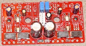
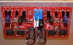
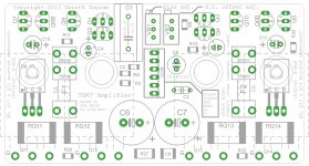
For the gentlemen to whom I recently sent a pair of shiny red pcb's you will find these images helpful.
It's probably obvious - but I mounted all the SMD parts first, then cleaned up the flux off the board before proceeding to add the through-hole parts. It's handy to set the dc-offset trimmer to it's mid point (using ohmeter) before you install it, and to set the bias trimmer to represent the minimum (I guess zero) resistance within the circuit so that the amp powers up with lowest idle current first time you try it.
I also scratched into the plastic, on the sides of the BD139/140 devices, their identity since you can't read the manufacturers labels once they're mounted face-up to the board. I figured if something didn't work I would be grateful of the chance to do a quick check that they were installed properly. I also slipped in a piece of thermal pad between the BD130/140 devices and the power FETs to ensure good thermal contact between them when the amp is bolted onto the heatsink - for good temperature sensing. It's a bit fiddly to get the leads on these devices just right so that the mounting holes in the devices line up with the mounting holes in the pcb and subsequently with the heatsink. The mounting holes in the pcb are slightly over-sized to allow for some tolerance.
There is a resistor in parallel with each fuse, RF!, RF2 to fit on the underside. This was a feature from some of my older designs where the idea is to keep the rail voltage up even if the fuse blows to avoid the output swinging to one rail if only one fuse blows. They need to be 100 Ohm. You may not want to install them - it's optional. Greg recommends setting bias current with fuses removed and a 10 Ohm resistor across the fuse holder so you can measure the voltage across it.
Also on the underside are CZ1 and CZ2. These were not installed. I included them as an option to install across the gate-drainof the power FETs, before the gate stoppers as a means to essentially slow down the FETs if stability was a problem. I have not used them as they appear unnecessary with the FETs Greg recommends.
If using QFETs then I recommend using something like 220pF for CZ1 and CZ2. You also have to modify the temperature compensation sensitivity by adjusting the values of resistors in the current source. I haven't established proven values but R10/12 have to be lower in value (e.g. 330R).
Be careful of choice of connector header and C1 so that they do not interfere - some connectors may have protrusions that move when you plug/unplug from them. The one's I used were just fine.
I did not install C12 and C13, the bypass caps for the rail decoupling capacitors. I'm not convinced they are of value but I kept the pads there in case I wanted to add them in the future. Modern electrolytics are much better than they used to be such that the bigger issue is usually inductance of the wiring - with the caps close to the outputs I don't envisage much benefit from additional bypassing.
Earthing: I will report on this once I've completed my own build. My plan is to run the speaker return directly back to the amplifier power ground and then from there run a wire from each amplifier power ground back to the start earth at the power supply. YMMV
Attachments
Last edited:
Member
Joined 2009
Paid Member
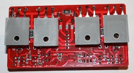
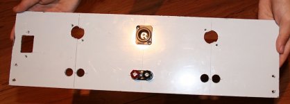
Seems like this hobby is more about using a drill than a soldering iron. I'm drilling holes in chasis, in speaker braces, once it was in pcb's. Today it was making holes in a blank piece of aluminium for the back panel (those aren't my hands in the photo).
Attachments
- Home
- Amplifiers
- Solid State
- TGM7 - an amplifier based on Greg Ball SKA