Hi
As for fuse holders, I like these from Keystone Electronics. They hold either ATC or the smaller ATM fuses. Also there are SMD fuses available, even in 0603 size!
As for gate stoppers and instability, you can try a gate Zobel, a zero ~120R in series with 47pf from gate to drain on the mosfet side of the gate stopper as close to the device package as possible. I have never used this with regard to power mosfets as common source amplifier but the internal workings of the mosfet should be the same on this level.
Last edited:
Member
Joined 2009
Paid Member
Hi,
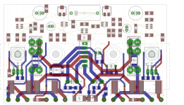
Well I've managed to put the gate stoppers at the gate pins - I think this is the best approach. The suggestion to include gate zobel's is interesting, but not sure I have the space for it.
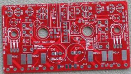
I've attached my work-in-progress on the layout, so far just the high-current circuits are in place.
In the past I've used little metal clips for the fuses, a separate one for each end of the fuse. But including both 15mm and 20mm spacing on the pcb I can choose when I build whether to build for 15mm or 20mm fuses. I hadn't considered the SMD fuses - I did use one on my TGM5. I'll check out the options on digikey.
Well I've managed to put the gate stoppers at the gate pins - I think this is the best approach. The suggestion to include gate zobel's is interesting, but not sure I have the space for it.
I've attached my work-in-progress on the layout, so far just the high-current circuits are in place.
In the past I've used little metal clips for the fuses, a separate one for each end of the fuse. But including both 15mm and 20mm spacing on the pcb I can choose when I build whether to build for 15mm or 20mm fuses. I hadn't considered the SMD fuses - I did use one on my TGM5. I'll check out the options on digikey.
Attachments
Member
Joined 2009
Paid Member
Well, I nearly finished the layout when I had sober second thoughts about using the dual-transistor SMD parts because of ease of use. Soldering 1206 resistors is easy and SOT-23 transistors is quite doable because the 3 legs are far apart (which means they end up being same size as a TO-92 footprint!). But the dual pairs come with 6 legs and even though they are bigger than the SOT-363 I used in TGM5 I think they will be a nuisance. They will be harder to install, harder to replace or repair and future availability is unknown. So I've reverted to good old TO-92's and I can now use the parts recommended by Greg if I want to 😱
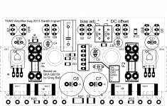
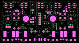
The LTP pairs and the drivers are mounted face-to-face so they will track thermally. A single socket on the board is used for all signals. I also added a pair of diodes (opposite polarities) in parallel with the ground lift resistor to protect it from error conditions on the ground.
Since the pcb will be mounted against the heatsink the board will be oriented vertically I've specified side adjusting trimpots as they will be easier to access (from above the chasis) for adjustment.
The board size has come out around 96mm x 52mm. It would be nice to shave it down to 96mm x 50mm but I'm not sure the design rules will allow. I've never used an outside pcb house before so I will need to do some homework.
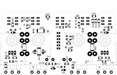
Attached is a component-only view of the top and the bottom side of the board. The bottom view doesn't show the temperature sensing devices (I may fixe this eventually).
The LTP pairs and the drivers are mounted face-to-face so they will track thermally. A single socket on the board is used for all signals. I also added a pair of diodes (opposite polarities) in parallel with the ground lift resistor to protect it from error conditions on the ground.
Since the pcb will be mounted against the heatsink the board will be oriented vertically I've specified side adjusting trimpots as they will be easier to access (from above the chasis) for adjustment.
The board size has come out around 96mm x 52mm. It would be nice to shave it down to 96mm x 50mm but I'm not sure the design rules will allow. I've never used an outside pcb house before so I will need to do some homework.
Attached is a component-only view of the top and the bottom side of the board. The bottom view doesn't show the temperature sensing devices (I may fixe this eventually).
Attachments
Last edited:
Beautifully neat layout, Gareth. If boards do become available, they will encourage me to try my first SMD's!
Last edited:
Member
Joined 2009
Paid Member
Thanks Stuey -
What I need now is a couple of recommended pcb vendors to use - that do genuine prototype double-sided pcbs with all-plated-through-holes, for good prices. Then I can check the design rules in more detail.
I did look on the web, but I'd feel better using a vendor somebody else has had a good experience with. One thing that worried me was I saw adverts for 2-layer boards that looked like both layers were on the same side of the pcb (?) which is no good.
Last edited:
Member
Joined 2009
Paid Member
I've seen a few recommendations on this forum but can't remember where and couldn't find them.
A few mentioned in this thread.
A few mentioned in this thread.
Last edited:
Member
Joined 2009
Paid Member
Hi Stuey, that's a good thread because it reminds us that cheapest is not always the lowest cost in the end - quality is important. I will check out two of the vendors recommended there.
By the way, I am also going to reconsider the use of the QFETs because I now understand more about this circuit and want to avoid having to tweak parts values to accommodate additional differences from the original design. It seem that Greg used two different options, IRFP240 and IRFP140. The latter has a 100V breakdown rating which still gives me significant derating for 50V supplies, otherwise they look very similar.
By the way, I am also going to reconsider the use of the QFETs because I now understand more about this circuit and want to avoid having to tweak parts values to accommodate additional differences from the original design. It seem that Greg used two different options, IRFP240 and IRFP140. The latter has a 100V breakdown rating which still gives me significant derating for 50V supplies, otherwise they look very similar.
Member
Joined 2009
Paid Member
I've found this thread: http://www.diyaudio.com/forums/parts/228190-dirt-cheap-prototype-pcb-manufactory.html This thread I just referenced indicates a number of happy users.
I've run the Eagle ERC - no issues. I've run the Eagle DRC - got drill size errors on the via's (there are very few via's) which all look just fine to me so it's a strange error. But what irritated the most was that I got over 500 Stop Mask errors. Jeeez. I downloaded the DRC (.dru) file from the vendor I'll probably use: ITEAD Studio - Make innovation easier and ran their DRC. The drill size errors went away but I still have 525 Stop Mask errors. I looked at several of them in detail and they look like complete nonesense that can be ignored.
Next step, I have to figure out how to create the Gerber files (not related to Gerbils I hope 😀 )
the IRF9140 is the limiting device.................. It seem that Greg used two different options, IRFP240 and IRFP140. The latter has a 100V breakdown rating which still gives me significant derating for 50V supplies, otherwise they look very similar.
If you use higher voltage supplies then it's the irf9240 that is the limiting device.
Member
Joined 2009
Paid Member
Member
Joined 2009
Paid Member
Hi Bigun, Can you change the ratio of the 3k resistor and the one in the current source to increase the compensations for the QFets?Fab
I'm not sure I understood you question at first, now I realize now that you are right about the impact of the 3k resistor (in the LTP collectors) affecting tempo. But it also determines the current through the LTP because the voltage drop across the 3k has to match the Vgs of the output FET (more or less). And it also has some influence on the gain of the LTP. I am seeing (through Spice and further thought) how much Greg has done to tweak the values of all the parts to find the best compromises in operating points.
Update: I have done some checking of the design:
1) Eagle schematic matches with my Spice schematic and GB150 where relevant
2) Pin outs are correct (Eagle has a different pin out for the small signal devices than indicated in the spec sheet from Digikey
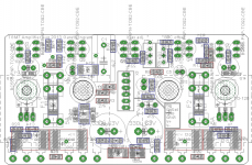
3) Checked spacing of traces for sufficient clearance for 100V rail-to-rail voltages (+/- 50V). Didn't like what I found. Seems that I have been working on the design with a zoomed-in view of life. I had to rip up half the layout and start over. I've settled for a compromise on some of the parts locations but I'm much happier with the layout of the traces - less complex, wider traces, better separation, shorter and I think more robust to manufacturing tolerances
4) lengthened the leads on the temp. sensing devices for a bit of tolerance in mounting to the heatsink. Likewise enlarged the mounting hole diameter by 1mm for a bit more tolerance
5) printed out and checked the gerber files. Noticed that text changes - Eagle defaults text to a 'proportional font' but conversion to gerber extracts it with fixed font so I changed the text in Eagle to 'fixed' font and that let me tidy it up.
6) ERC and DRC is clean (except Stop Mask)
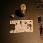
I thought I'd do a sanity check on physical size after losing track of the real size of things - see photo.
Perhaps you can recognize a couple of components in the photo that don't have a place on the pcb ? and if you look carefully you can see a 1206 size SMD resistor.
Attachments
Member
Joined 2009
Paid Member

Member
Joined 2009
Paid Member
Member
Joined 2009
Paid Member

Gareth,
You have dominant H3 - can you subordinate it to H2? It would sound a little 'edgy'.
Beautiful pcb design!
Hugh
You have dominant H3 - can you subordinate it to H2? It would sound a little 'edgy'.
Beautiful pcb design!
Hugh
Can you give us some clues on which techniques may allow this?................ can you subordinate it to H2? .............
Member
Joined 2009
Paid Member
Nelson did some studies and found 1/3 people prefer dominant H2, 1/3 prefer dominant H3 and 1/3 didn't have a preference. I have a Bryston symmetrical amplifier that sounds very good in my home theatre - so I know that for this application a dominant H3 is good.
However, distortion spectra measured for the SKA have been published on Greg's forum and they measured dominant H2. I believe that there is already asymmetry in this design due to component matching, N-MOS and P-MOS are different beasts.
It's easy to add asymmetry to produce more H2 into these amps, adjusting a resistor or two is a trivial option. I did this in TGM5 but didn't like the sound as much as the cleaner sound without the adjustment. I don't know why because I do like my AKSA clone and my tube amp which are both H2 dominant. Perhaps because for my home theatre I want less IM.
- Home
- Amplifiers
- Solid State
- TGM7 - an amplifier based on Greg Ball SKA